Overview
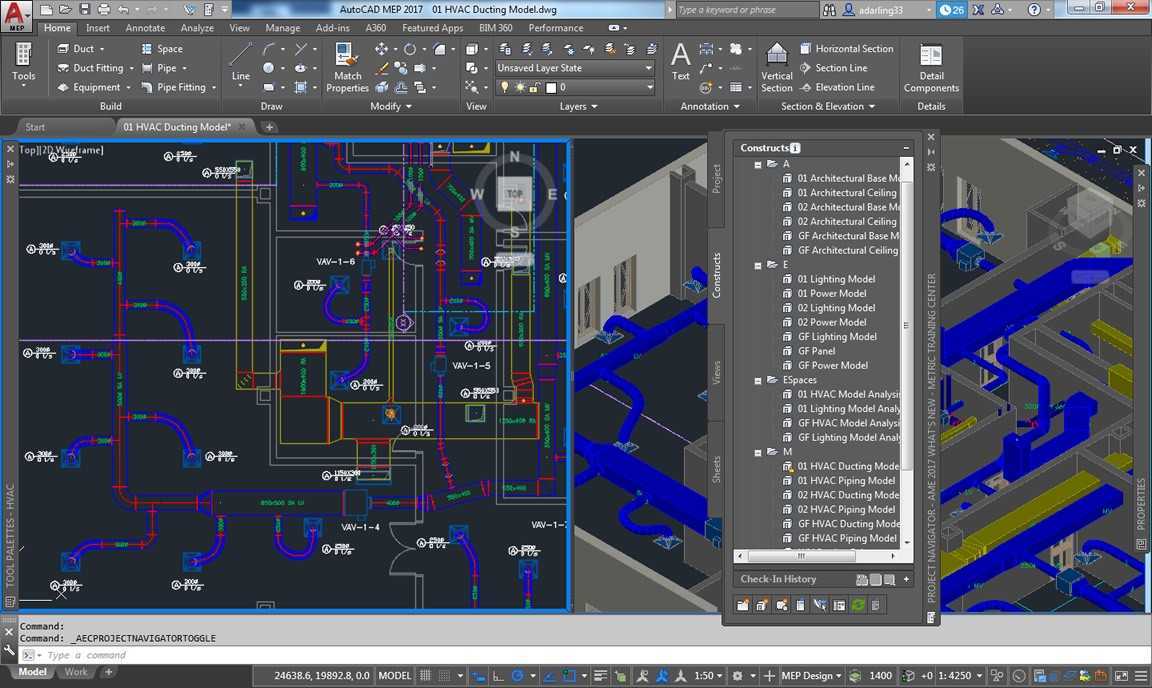
AutoCAD® MEP software helps you draft, design, and document building systems. Create more accurate designs and increase productivity within a familiar AutoCAD-based environment.
What's new
Collaboration
-

AutoCAD and AutoCAD Architecture support
Work on flat 2D or geometric floor plans.
-
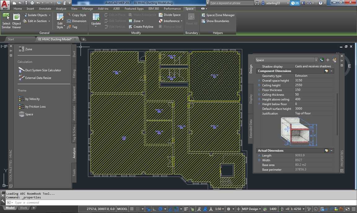
Automatic space and zone calculation
Calculate room measurements automatically.
-
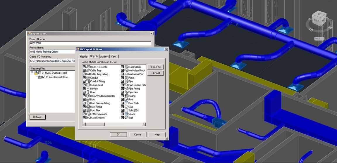
IFC data support
Create, manage, and share design data.
-
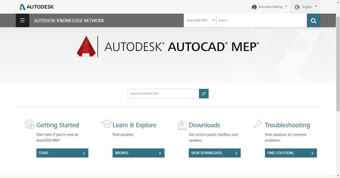
Web-based help and learning tools
Stay informed with tips and tricks and other content.
Construction & content
-
NEW
Section and elevation (enhanced)
Now edit Xrefs when editing live sections and refresh upon opening.
-
NEW
Parallel routing improvements
Select routing preferences for objects, then automatically connect parallel objects.
-
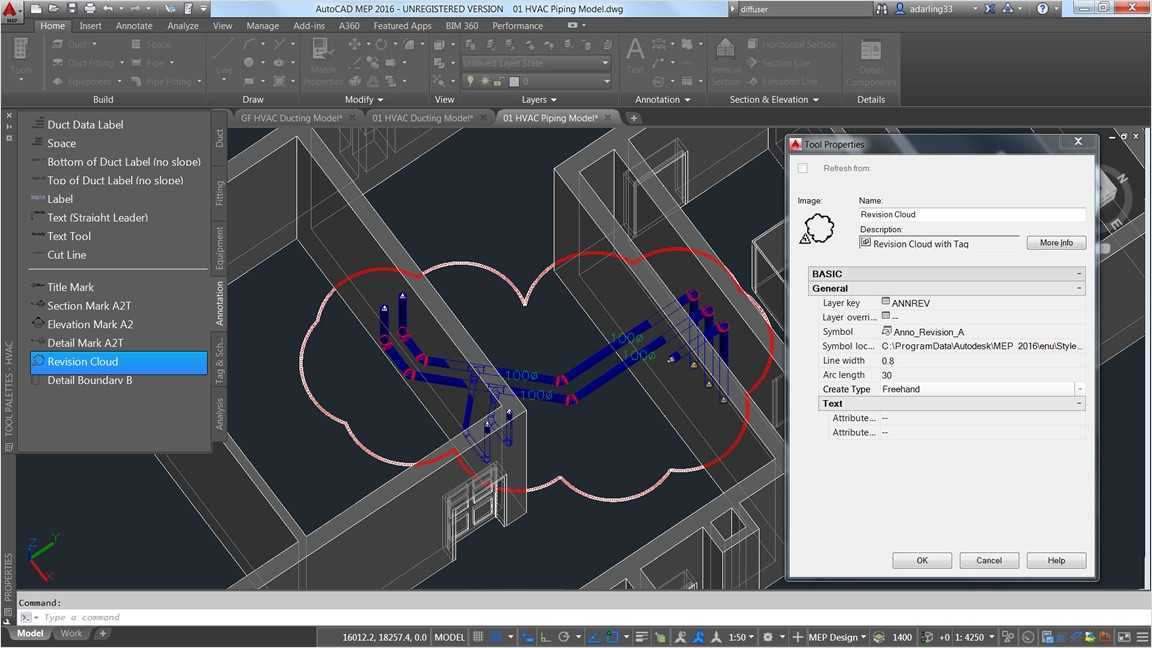
Revision cloud
Get a consistent appearance in views.
-
Documentation
Create, rationalize, and document 2D views.
-
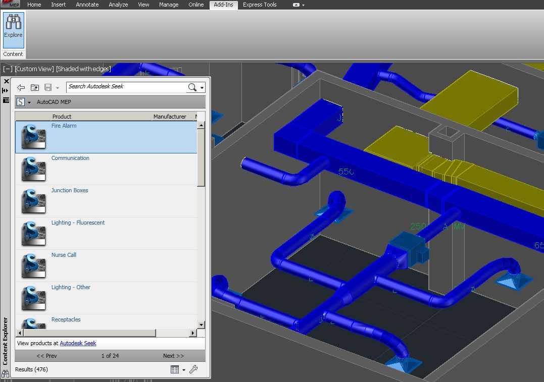
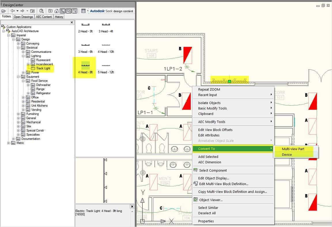
Integrated content search
Easily find design files, objects, and content.
-
AutoCAD block and symbol conversion
Batch-convert single or multiple blocks.
-
Drawing management
Create and manage MEP project drawing sheet sets.
-
Sloped pipe routing preferences
Use routing preferences with sloped piping. (video: 59 sec.)

Productivity & usability
-
NEW
Style Browser (enhanced)
Get more MEP components, and add folders to the Content Library.
-
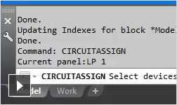
NEW
Assigning circuits
Change the circuit for a given set of devices.
-
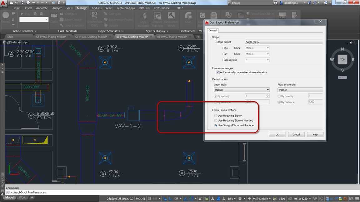
Elbow duct fittings
Choose the type of elbow that best fits your design.
-
Automated property set definitions
Complete quantity takeoff calculations.
-
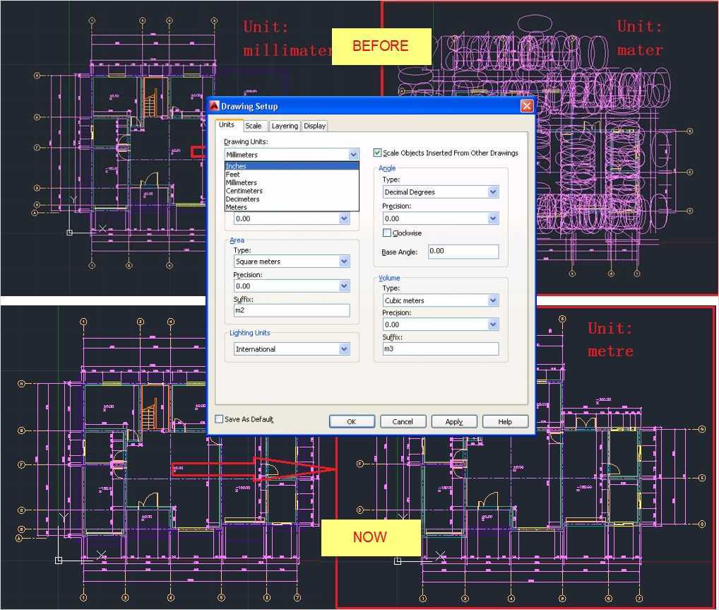
Annotation and unit scaling
Objects and text change along with drawing units.
-
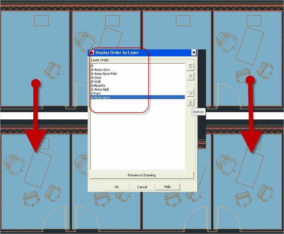
Display order by layer
Set an order for layers and preview your changes.
-
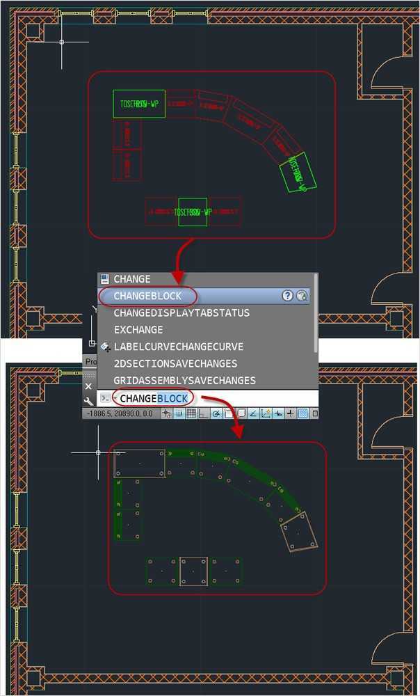
Block swap
Make changes to components as your design changes.
-
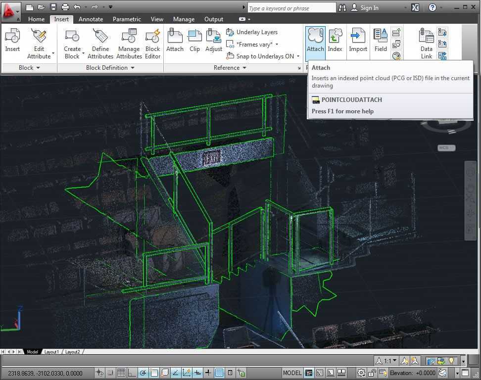
Point clouds
Use point cloud data for renovation projects.
-
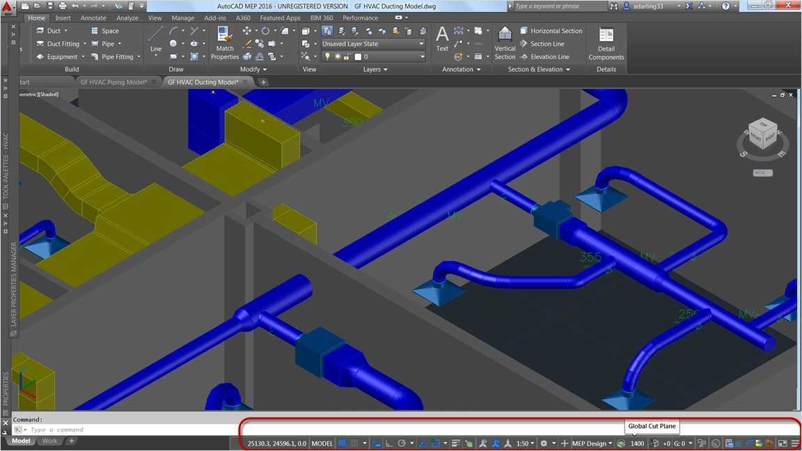
Status bar
Now includes Display Configuration, Cut Plane tools.
-
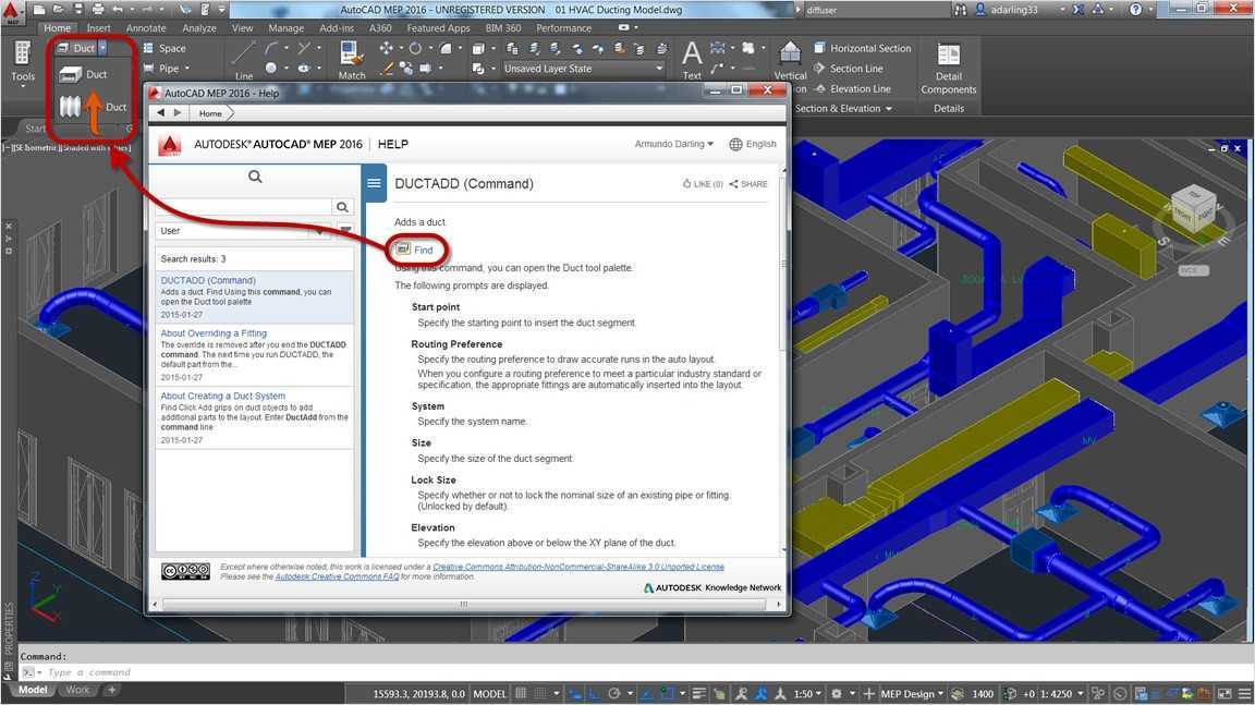
UI Finder
Locate frequently used commands from within Help.

About AutoCAD MEP Workflow
AutoCAD MEP provides features that allow the creation of very complex designs. While the software has many intricacies, there is a basic workflow for using it. Use the following table to navigate to detailed workflows for designing mechanical, electrical, and plumbing systems.
| General task | View more information | |
|---|---|---|
| Establish high-level project parameters, and create document sets | Define project standards, the look of the drawing area, the look of parts, the tool catalogs to use, and other settings. See Working with Drawing Management Projects. Create sheets, sheet lists, and cover sheets for construction document sets. See Construction Document Workflow. | |
| Link to architectural floor plans | Use Project Navigator to create cross references to the floor plans onto to which MEP designs will display. See Working with Referenced Drawings | |
| Create preliminary domain outlines using flow and 1-line diagrams | Use the schematic tool set in MEP to create concept designs. See About Schematic Diagrams | |
| Create detailed domain designs using catalog parts and custom content | Create:
|
|
| Circulate designs for review | Use Drawing Compare to see how drawings differ from one revision to another. See Comparing Drawings |
Working With Drawing Management Projects
When you create an AutoCAD MEP drawing, you often need to relate your layout to an architectural drawing, such as a floor plan, a reflected ceiling plan, or an AutoCAD MEP building model.
You can begin with a drawing that contains the walls and other spatial elements that you need by attaching another drawing called a referenced drawing or xref. Xrefs are drawings that are linked to, and displayed in, the current drawing.
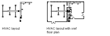
Whenever you open a drawing, the software reloads the xref drawings attached to it so that changes made to the xref drawings are reflected in your building system drawing. For example, if you attach an architectural floor plan as an xref, and the architect subsequently changes the location of the building’s mechanical room, the changes to the architectural floor plan are automatically reflected in your building systems drawing the next time that you open it. You can also reload xrefs on demand and check for interferences between building system objects and structural members by applying interference detection highlighting to your drawing.
There are 2 types of xrefs: attachment and overlay. Unlike an attached xref, an overlaid xref is not displayed when the drawing is itself attached or overlaid as an xref to another drawing—a process referred to as nesting xrefs. Overlaid xrefs are designed for data sharing in a network environment. By overlaying an xref, you can see how your drawing relates to the drawings of other groups without changing your drawing by attaching an xref. Changes made to an xref drawing, whether attached or overlaid, are displayed in your drawing when you open the drawing or reload the xref.
Linking xrefs to your drawings is effective when creating design drawings and construction documents. Design projects typically involve the coordination of many drawings, and sharing the content of those drawings is fundamental to efficient project management. Establishing standards for using xrefs helps you to use drawings optimally and minimize the need to re-create drawing content.
The following cite several advantages to using xrefs in AutoCAD MEP drawings:
- You can reference an architectural drawing as a base for your mechanical, electrical, or plumbing drawings. In addition, you are aware immediately of any changes to the architectural drawing because the changes are reflected when you open your drawing or reload the xref.
- You can assemble master drawings from individual design drawings. For example, several people can work with different sections of a design for a large building (such as by floor or by wing), and the individual designs can be referenced into a master drawing.
- You can attach drawings containing borders, title blocks, and other office standards for plotting as xrefs for easy maintenance.
- You can choose not to load an xref if you do not need it as a reference. The xref does not use system resources when it is not loaded.
Construction Document Workflow
It is recommended that project drawings are created, stored, and managed using the drawing management tools in AutoCAD MEP. When you use Project Navigator to manage drawings, you can efficiently create construction documents that reference the building system drawings.
After you create a project, you can manage drawings from a central location. For more information, see Working with Drawing Management Projects.
A typical workflow for creating documents with AutoCAD MEP is as follows:
| Step | View more information | |
|---|---|---|
| Create a construct | Save your drawing as a construct on the Constructs tab in Project Navigator. See Creating Construction Documents. | |
| Create views | Create views for drawings and schedules to be included in sheets. See Views. | |
| Create sheets | Create sheet drawings for publishing and plotting. Place view drawings on the appropriate sheets. See Creating a Sheet. | |
| Create sheet sets | Create a sheet set that includes a cover sheet with a sheet list. See Ordering Sheets in the Sheet Set. | |
| Issue construction documents | Plot or publish the sheet set. You can publish a sheet set directly to Design Web Format (DWF™). See Publishing a Sheet Set to DWF™. |
Working With Referenced Drawings
When you create an AutoCAD MEP drawing, you often need to relate your layout to an architectural drawing, such as a floor plan, a reflected ceiling plan, or an AutoCAD MEP building model.
You can begin with a drawing that contains the walls and other spatial elements that you need by attaching another drawing called a referenced drawing or xref. Xrefs are drawings that are linked to, and displayed in, the current drawing.
Whenever you open a drawing, the software reloads the xref drawings attached to it so that changes made to the xref drawings are reflected in your building system drawing. For example, if you attach an architectural floor plan as an xref, and the architect subsequently changes the location of the building’s mechanical room, the changes to the architectural floor plan are automatically reflected in your building systems drawing the next time that you open it. You can also reload xrefs on demand and check for interferences between building system objects and structural members by applying interference detection highlighting to your drawing.
There are 2 types of xrefs: attachment and overlay. Unlike an attached xref, an overlaid xref is not displayed when the drawing is itself attached or overlaid as an xref to another drawing—a process referred to as nesting xrefs. Overlaid xrefs are designed for data sharing in a network environment. By overlaying an xref, you can see how your drawing relates to the drawings of other groups without changing your drawing by attaching an xref. Changes made to an xref drawing, whether attached or overlaid, are displayed in your drawing when you open the drawing or reload the xref.
Linking xrefs to your drawings is effective when creating design drawings and construction documents. Design projects typically involve the coordination of many drawings, and sharing the content of those drawings is fundamental to efficient project management. Establishing standards for using xrefs helps you to use drawings optimally and minimize the need to re-create drawing content.
The following cite several advantages to using xrefs in AutoCAD MEP drawings:
- You can reference an architectural drawing as a base for your mechanical, electrical, or plumbing drawings. In addition, you are aware immediately of any changes to the architectural drawing because the changes are reflected when you open your drawing or reload the xref.
- You can assemble master drawings from individual design drawings. For example, several people can work with different sections of a design for a large building (such as by floor or by wing), and the individual designs can be referenced into a master drawing.
- You can attach drawings containing borders, title blocks, and other office standards for plotting as xrefs for easy maintenance.
- You can choose not to load an xref if you do not need it as a reference. The xref does not use system resources when it is not loaded.
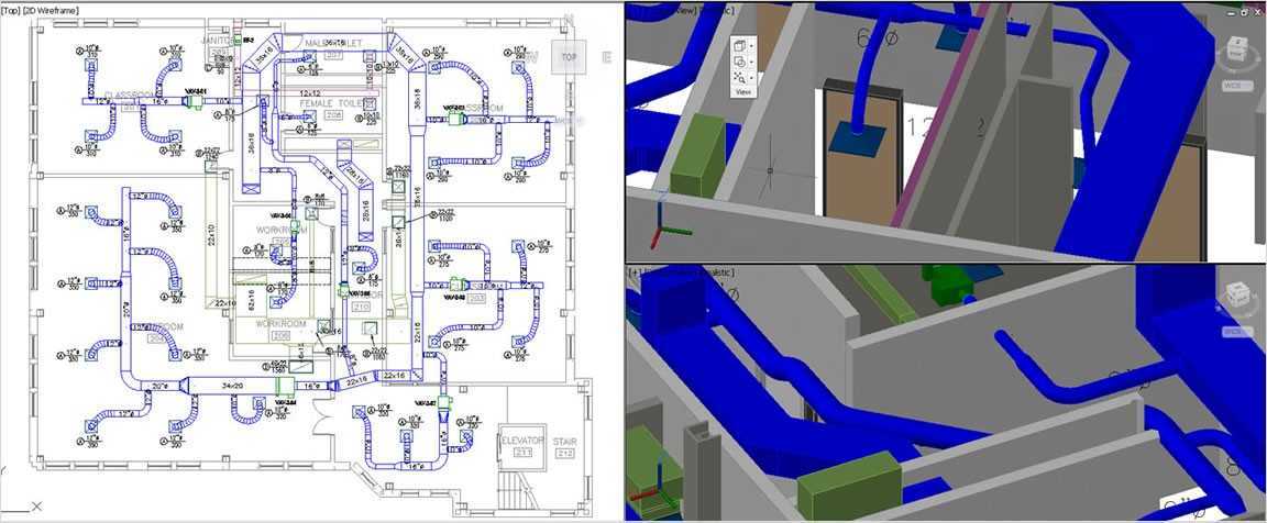
HVAC System Overview
Best practices for mechanical system design start with the establishment of project parameters. HVAC designers can design duct and necessary piping systems to create, size, and connect heating and cooling components.
Use AutoCAD MEP to design and draft heating, ventilation, and air conditioning (HVAC) systems for a building plan.
Before you begin drafting, you can establish design preferences and HVAC system definitions that fit your project. Once you define the systems for your drawing, you can assign systems to equipment and ductwork as you draw and modify your duct networks.
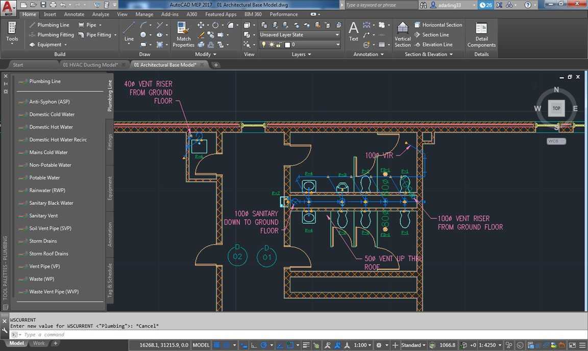
Plumbing Design Workflow
A typical workflow using AutoCAD MEP to design a plumbing system includes the following steps:
| Step | View more information | |
|---|---|---|
| Configure system settings | Control the form and function of objects in your drawings by specifying design preferences. See About Drawing Preferences and About Configuring Plumbing System Settings. | |
| Set up a project | Specify standards (for example, the templates and tool catalogs to use), and integrate the plumbing system plans with the architectural plans. See About Working With Drawing Management Projects. | |
| Set up a pipe sizing table | Specify the fixture unit table and plumbing line sizing table (pipe sizing table). See About Configuring Fixture Unit Tables and To Specify Plumbing Line Sizing Tables. | |
| Open a drawing and attach architectural plan | Use Project Navigator and attach an architectural floor plan as an external reference. See About Working with External Reference Files. | |
| Add pumps, water heaters, drains, showers, sinks or other equipment | Place the plumbing equipment and fixtures on the floor plan. See To Add Plumbing Equipment and Fixtures. | |
| Add pipe to connect equipment | Connect the equipment and fixtures using plumbing lines. See About Adding Plumbing Lines. | |
| Size the plumbing lines | Analyze the plumbing system to properly size the components. See About Calculating the Sizes of Supply Plumbing Lines or About Calculating the Sizes of Sanitary Plumbing Lines. | |
| Modify the layout | Modify the layout of the system to reflect required design changes, and recalculate sizes as necessary. See About Modifying Plumbing Systems. | |
| Draw a 1-line plumbing isometric | Use schematic tools to produce a drawing of the plumbing system for inspection by code officers. See About Schematic Diagrams. | |
| Label the plumbing system | Annotate the system as you lay it out to generate schedules and construction documents. See About Annotation. |
Radiant Heating Systems
Refer to the following workflow for creating and modifying radiator systems:
| Review the steps | View more information |
|---|---|
| Set up a project | Specify tool catalogs to use and other project information. See Working with Projects |
| Import radiator data files | Use the BDH files that contain radiator data in your drawings. See Creating Radiator Parts |
| Place radiators in drawing | Use windows and walls to locate and orient radiators. See Adding a Radiator MvPart |
| Run parallel supply and return pipes | Place hot and cold radiator feed and return pipes in your drawings. See Adding Parallel Pipes to a Radiant Heating System |
| Add radiator valves and branch pipes | Prepare to connect radiators to pipes by adding valves and branches. See Adding a Radiator Valve |
| Copy valves and branch pipes to other radiators | Connect a set of specified radiators to a piping system. See Connecting Multiple Radiators to Parallel Pipes |
| Modify radiators as the design changes | Update a radiant heating system to accommodate design changes. See Modifying a Radiator MvPart |
| Add labels and annotations | Prepare your drawings for publication as construction documents. See Creating Construction Documents |
Workflow for Designing a Pipe System
| Review the steps | View more information | |
|---|---|---|
|
Set up a project and open a drawing. |
Specify standards for pipe systems. Attach the drawing to an architectural floor plan as an external reference. | |
| Create a preliminary 1-line conceptual design. | Prepare a conceptual design for evaluation by code officers and senior engineers. | |
|
Specify the pipes and fittings to be used as you draw a pipe run. |
Define piping design specifications for AutoCAD MEP to use when laying out the pipe run. | |
| Specify system definitions for chilled water or steam systems, size ranges, and display properties. | Define the look of your piping layouts. | |
| Add boilers, chillers, pumps, heat exchangers and other equipment. | Place equipment in a drawing. | |
| Connect equipment along pipe runs and layout the pipe system (sloped or non-sloped). | Configure pipe settings and pipe layout preferences, and apply routing solutions. | |
| Modify the pipe layout. | Refine portions of the existing layout. | |
| Generate construction documents. | Annotate the system as you place objects. Then, create construction documents. |
Comparing Drawings
A typical project requires multiple reviews at various stages in the project life cycle. When you send drawings out for review and comment, often you receive drawings containing proposed changes in return. The Drawing Compare feature allows you to visually compare the different versions and review proposed changes from architects and other engineering disciplines.
Like the traditional method of overlaying trace onto project drawings, visual cues indicate the status of drawings being compared and the state of the objects being reviewed. In addition, information is provided about changes to the properties of the objects.
Videos