![PERFORM3D_weblogo__150pxh_white_210202[1]](https://www.ace-hellas.gr/wp-content/uploads/2021/11/PERFORM3D_weblogo__150pxh_white_2102021.png)
PERFORMANCE-BASED DESIGN OF 3D STRUCTURES
Description
| Knowledge Base | |
|
|
|
| PERFORM-3D Releases | |
|
|
|
| 8.0.0 Released 15-Jun-2021
Released 15-Jun-2021 |
|
|
|
|
Traditionally, earthquake-resistant design has been strength-based, using linear elastic analysis. Since inelastic behavior is usually allowed for strong earthquakes, this is not entirely rational. Strength-based design considers inelastic behavior only implicitly. Displacement-based (or deformation-based) design considers inelastic behavior explicitly, using nonlinear inelastic analysis. Displacement-based design recognizes that in a strong earthquake, inelastic deformation (or ductility) can be more important than strength. PERFORM-3D allows you to use displacement-based design.
Procedures for displacement-based design using inelastic analysis are specified in ASCE 41, “Seismic Rehabilitation of Existing Buildings”. ASCE 41 applies to the retrofit of existing buildings, but the procedures can be applied to the design of new buildings. PERFORM-3D implements the procedures in ASCE 41. However, PERFORM-3D is a general tool for implementing displacement-based design. It is not limited to ASCE 41.
Structural Components
Elements
PERFORM-3D includes the following element types:
- Frame element for beams, columns and braces.
- Wall element for shear walls.
- Slab element for floors.
- Bar elements (with only axial stiffness) of various types.
- Buckling restrained brace.
- Gap elements.
- Seismic isolators of rubber and friction pendulum type.
- Fluid damper, with nonlinear relationship between force and deformation rate.
- Connection panel zone, to model shear deformation in beam-to-column connections.
- Infill panel, with only shear strength and stiffness.
- Deformation “gages” of various types. These elements have no stiffness . They are used for calculating deformations, and hence deformation demand/capacity ratios.
Components
In PERFORM-3D, most elements are made up of a number of components. For example, a beam element might consist of several components.
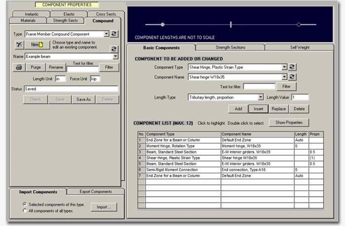
Component Properties
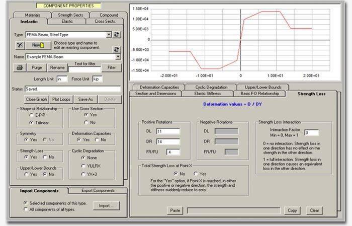
All inelastic components have essentially the same force-deformation relationship. This is a basic tri-linear relationship, with optional strength loss that can be captured in PERFORM-3D.
Hysteresis Loops
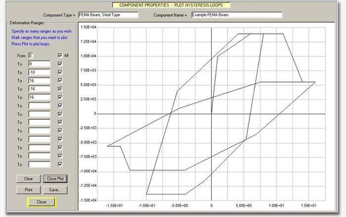
The hysteresis loop for an inelastic component can be varied to account for stiffness degradation. The loop can be plotted to check that it has the expected shape.
Deformation Capacities
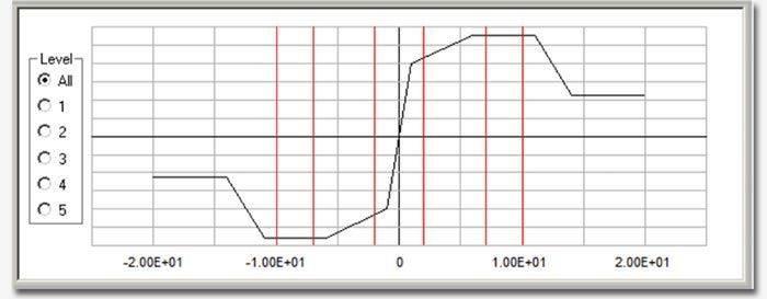
Deformation capacities can be specified for inelastic components, for calculating deformation demand/capacity ratios. Deformation capacities can be specified for up to 5 performance levels.
Demand/Capacity Ratios
PERFORM-3D includes a large number of components, both inelastic and elastic. During an analysis, D/C ratios are calculated as follows:
- Deformation D/C ratios are calculated for inelastic components.
- Hence, components that are allowed to become inelastic can be checked to make sure they have sufficient ductility.
- Strength D/C ratios are calculated for elastic components.
- Hence, components that are required to remain essentially elastic can be checked to make sure they have sufficient strength.
Limit States
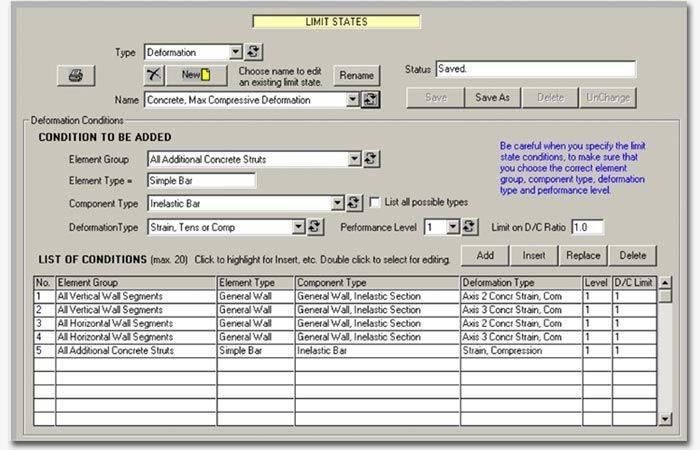
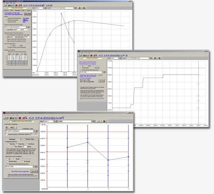
The number of components with D/C ratios can be very large. To simplify decision making, components that have similar D/C measures can be grouped into Limit States. An example D/C measure is the concrete tension strain in a shear wall. Each limit state has a “usage ratio”, which is the maximum D/C ratio for any component in the limit state. For a structure to satisfy the performance requirements, the usage ratios for all limit states should not exceed 1.0.
Frame Structures
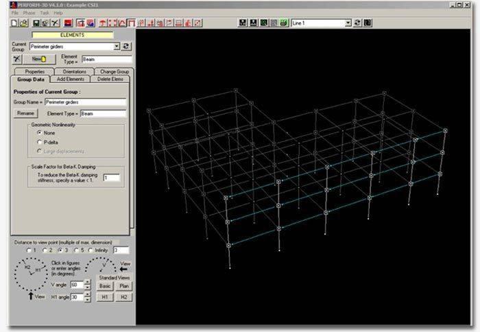
Simple frame structures consist of beam and column elements. Beam and column elements can be made up of a variety of components, and may be elastic or inelastic. P-delta effects can be considered or ignored.
Shear Wall Structures
Shear walls are modeled using plane wall elements. Complex shear cores are made up of plane elements. Wall elements can have inelastic behavior in bending and shear. Coupling beams are usually modeled using beam elements, with inelastic behavior in either bending or shear.
Analysis
Behavior Check
Behavior Check Tools
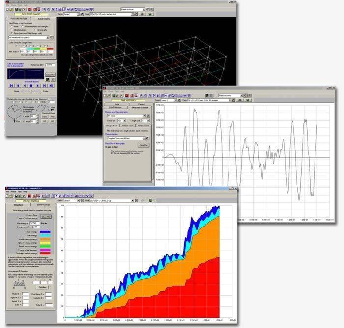
PERFORM-3D includes a number of tools for processing the analysis results. One set of tools allows you to study the behavior of a structure, and to check that the analysis look reasonable. These tools are as follows:
- Deflected shapes. These can be animated, for both static push-over and dynamic response history analysis.
- Time histories of many response quantities, including node displacements, velocities and accelerations; element and component forces and deformations; and forces on “structure sections” that cut through all or parts of the structure.
- Hysteresis loops for inelastic components.
- Moment and shear diagrams for beams, columns, and shear walls. These can be animated.
- Energy balance, showing strain energy, kinetic energy, inelastic work, and damping energy. This includes a comparison of external and internal work, which provides a good indication of the numerical accuracy of the analysis.
These tools are not directly useful for making design decisions. For this, see the next section, Performance Assessment
Performance Assessment
Import and Export
ACE-Hellas S.A.
Integrated Solutions
