NEW IN ARCHLINE.XP
We understand our users. We know what they need: powerful design tools, and visuals, as photorealistic as possible. This is what we deliver with our new version.
ARCHLINE.XP – THE GATEWAY TO BIM
ARCHLine.XP is professional design software for BIM (Building Information Modelling), to create architectural, interior design and furniture design projects.
Collaborate with co-designers through the IFC, DWG™, and RVT™ formats.
Easy to learn, easy to use CAD/BIM software with a fair pricing model.
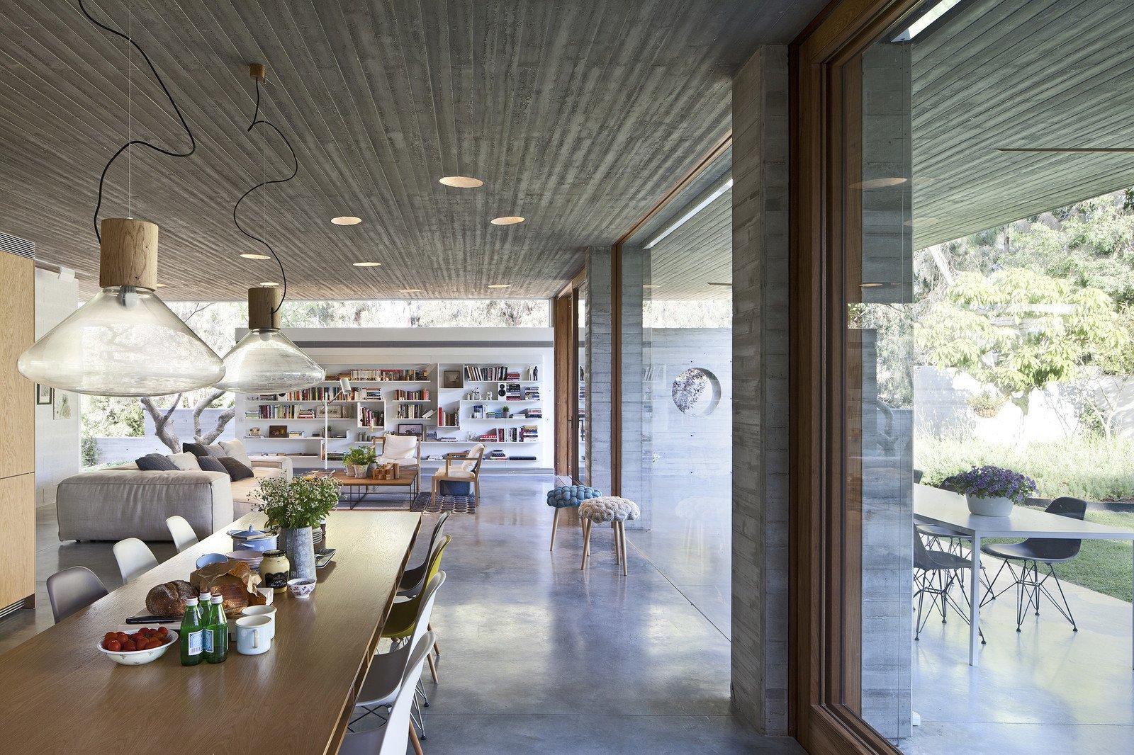
ARCHITECTURAL AND INTERIOR DESIGN ON A WHOLE NEW LEVEL
ARCHLine.XP is an architectural design software for BIM (Building Information Modeling), including features for interior design and decoration projects.
ARCHLine.XP supports the multi-disciplinary design process. It helps you to collaborate with co-designers through the IFC, DWG™, and RVT™ formats.
The software includes the whole process of architectural design, interior design and the planning of bespoke furniture.
The complete floor plan, 3D model and project documentation can be created within the software – the furnishing, tiling, lighting processes are fast and easy.
The section views, construction details, printing layouts, schedules, Excel reports, and renderings can be created with just a few clicks.
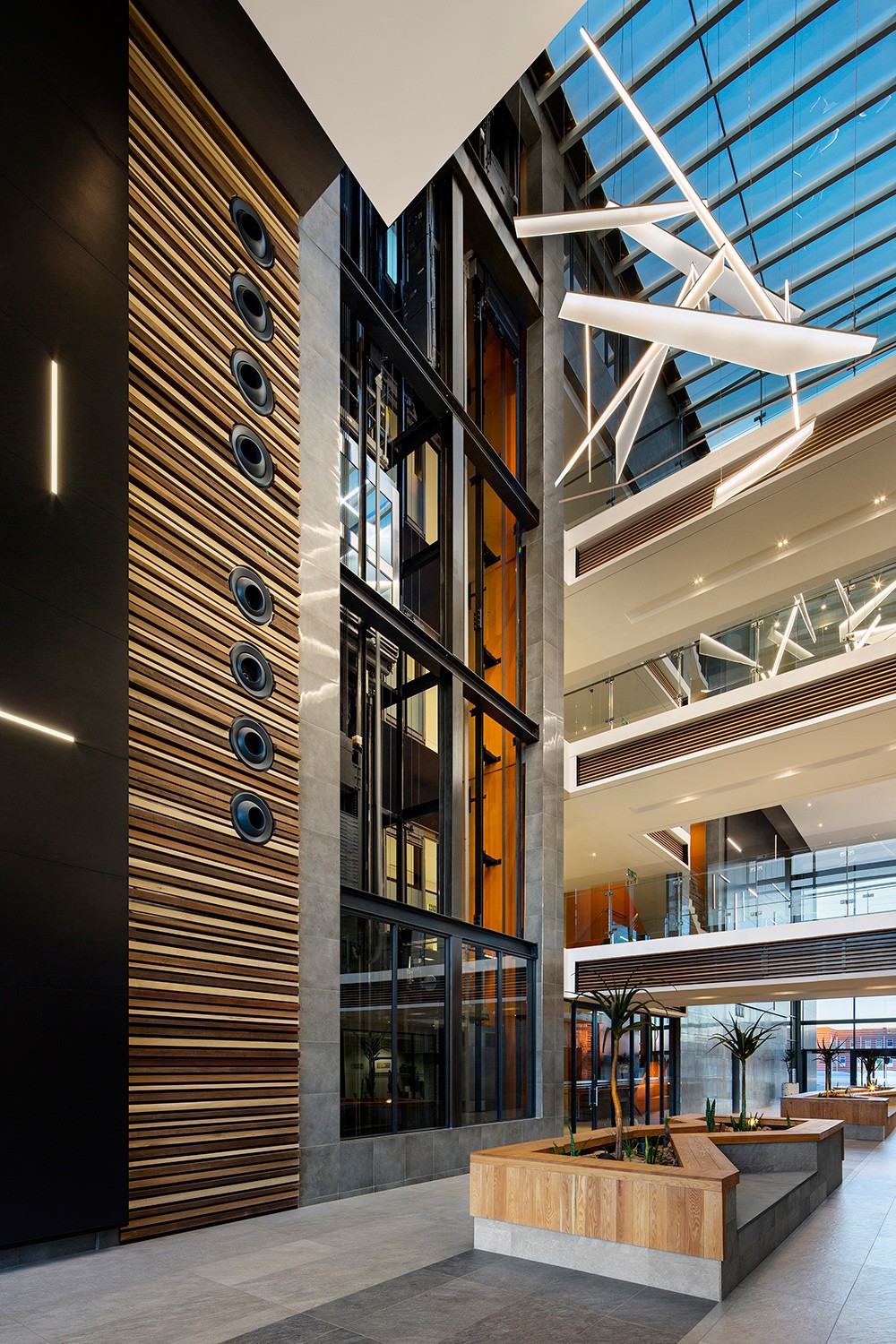
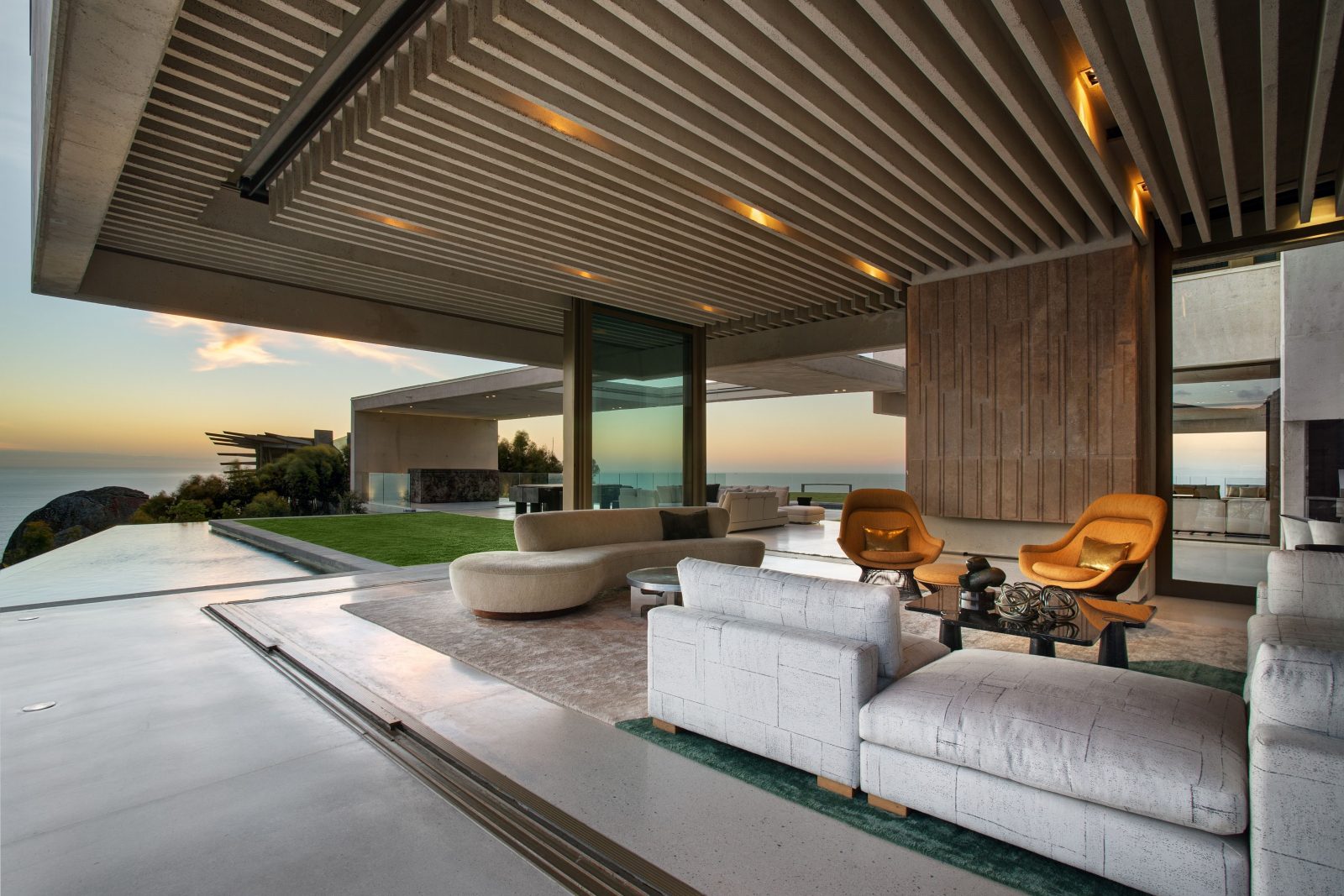
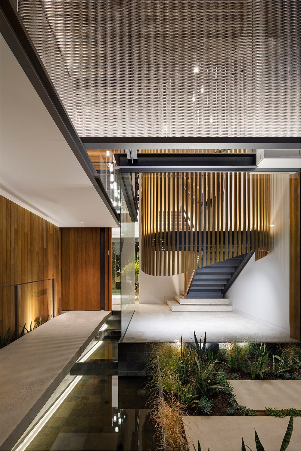
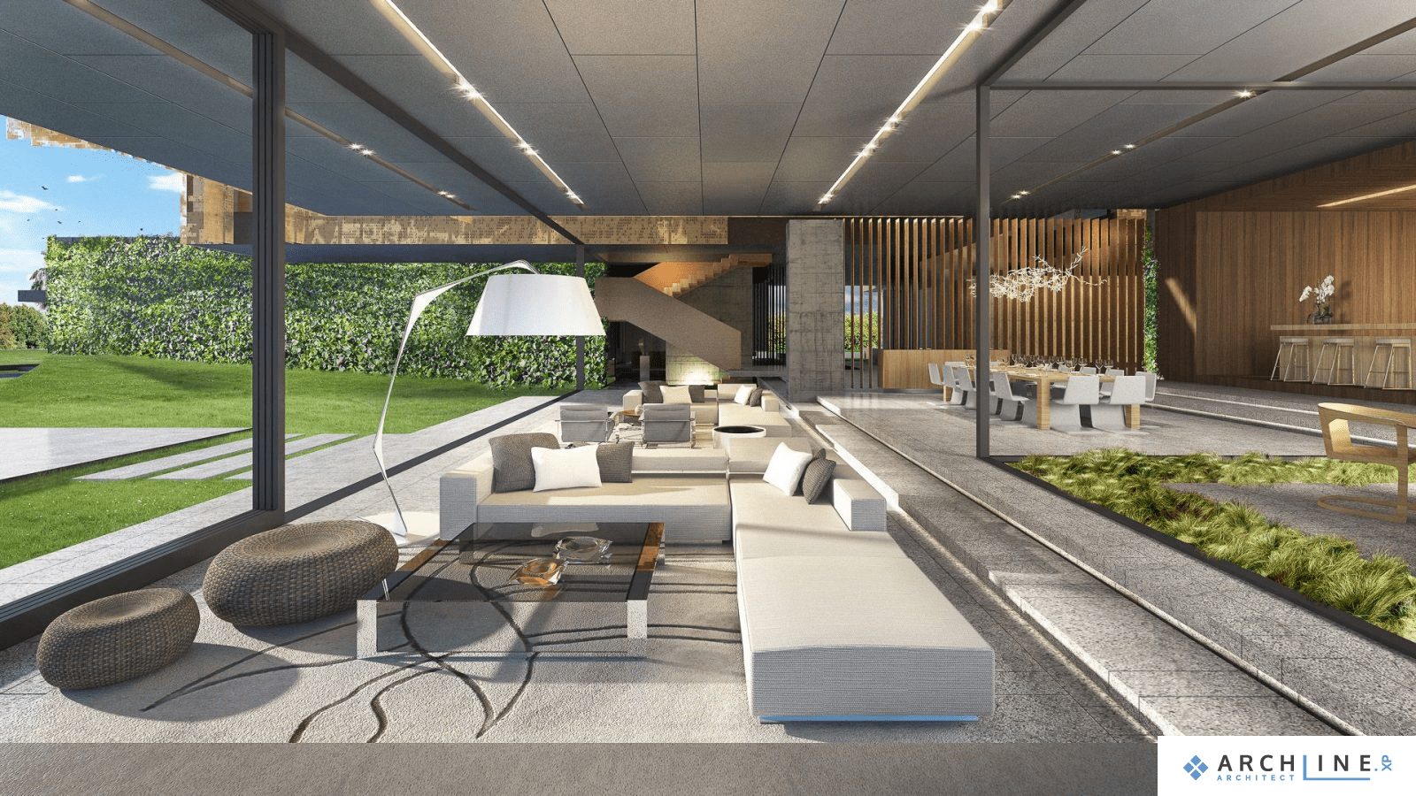
VISUAL DESIGN
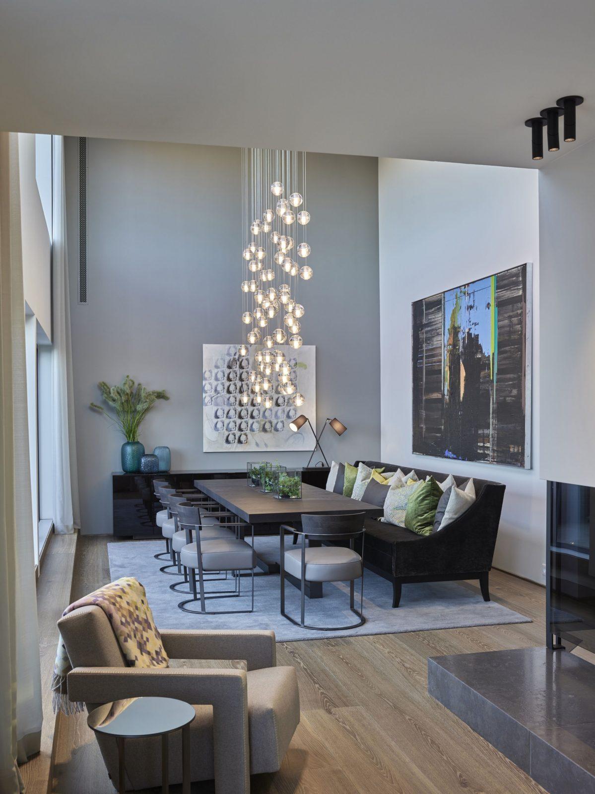
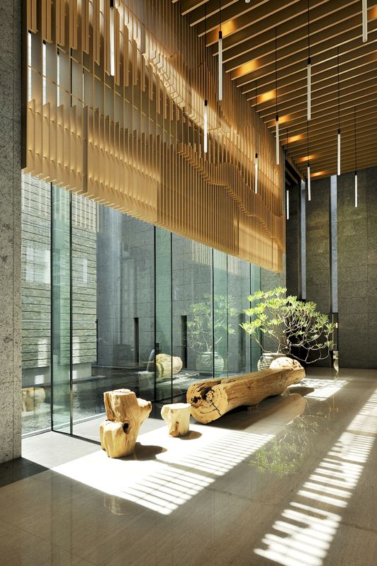
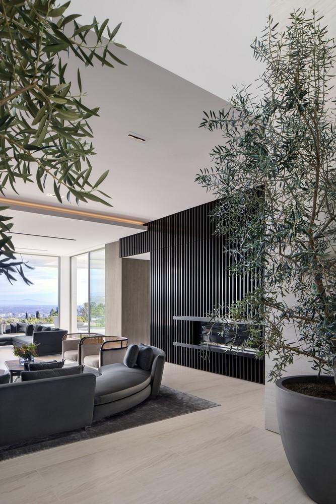
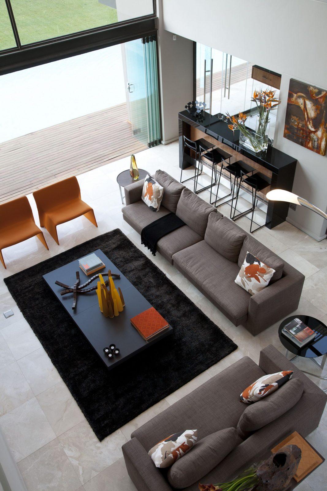
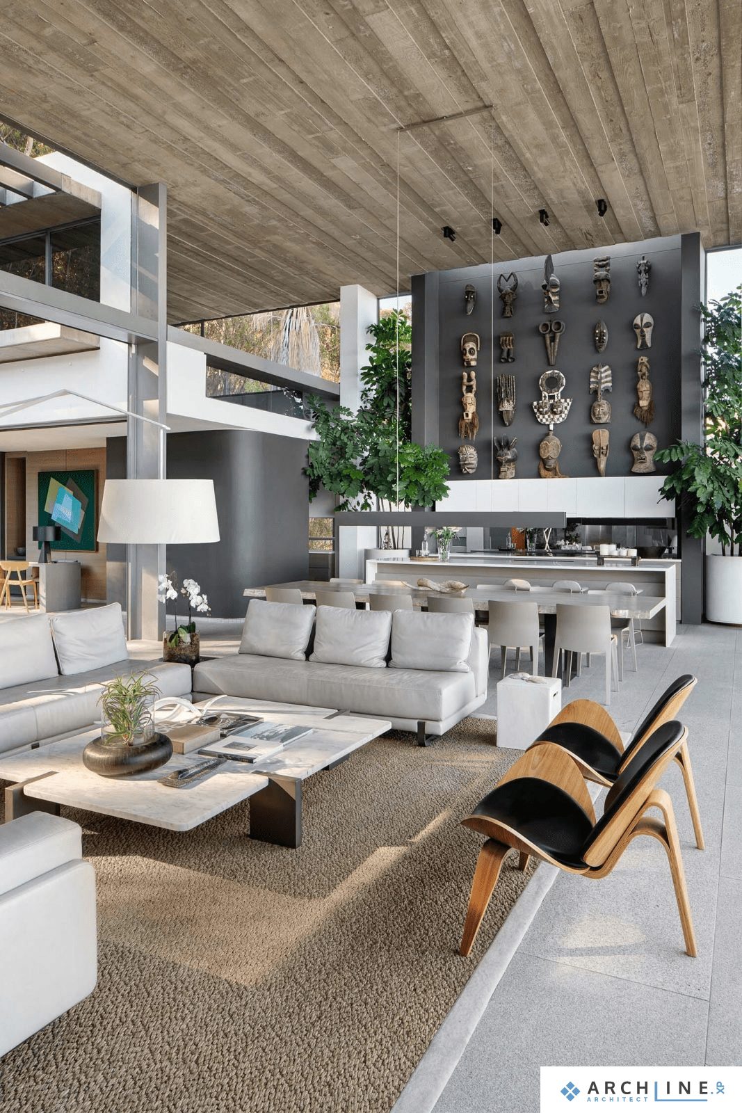
Visualization is a key part of the interior designer practise. High-quality and impressive presentations greatly affect the customer’s decision. The sight of the near future will almost certainly stir up each clients’ emotions, and every designer knows how influential of the customers’ first reaction can be.
A poorly managed presentation can undermine a thoughtful, technically carefully designed plan, while beautifully executed visuals can make all the difference.
Use the architectural floorplans, sections, and wall views to aid your work. When it comes to presentation to your clients, rely on our photorealistic renders, mood boards, or even allow your client to enter the plan, with the aid of our 360 virtual panoramic view.
ARCHITECTURAL AND INTERIOR DESIGN ON A WHOLE NEW LEVEL
ARCHLine.XP is an architectural design software for BIM (Building Information Modeling), including features for interior design and decoration projects.
ARCHLine.XP supports the multi-disciplinary design process. It helps you to collaborate with co-designers through the IFC, DWG™, and RVT™ formats.
The software includes the whole process of architectural design, interior design and the planning of bespoke furniture.
The complete floor plan, 3D model and project documentation can be created within the software – the furnishing, tiling, lighting processes are fast and easy.
The section views, construction details, printing layouts, schedules, Excel reports, and renderings can be created with just a few clicks.
VISUAL DESIGN
Visualization is a key part of the interior designer practise. High-quality and impressive presentations greatly affect the customer’s decision. The sight of the near future will almost certainly stir up each clients’ emotions, and every designer knows how influential of the customers’ first reaction can be.
A poorly managed presentation can undermine a thoughtful, technically carefully designed plan, while beautifully executed visuals can make all the difference.
Use the architectural floorplans, sections, and wall views to aid your work. When it comes to presentation to your clients, rely on our photorealistic renders, mood boards, or even allow your client to enter the plan, with the aid of our 360 virtual panoramic view.
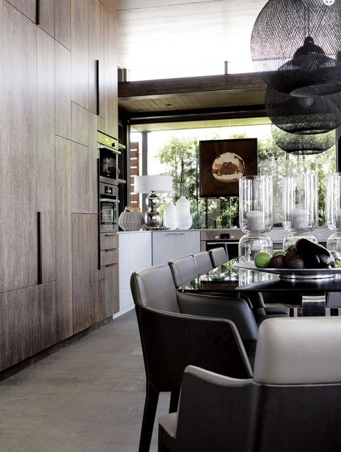
FURNITURE DESIGN
Bring your plan to life with the aid of furniture. Download objects from the 3D Warehouse straight into your plan, or use our built-in models.
Couldn’t find what you were looking for? Create your own! Design cabinets, KBB elements, and many more. Customize size, style, the surface finishes to test multiple versions of the same layout in just minutes and keep the one you like best.
DOWNLOADABLE MANUFACTURER PRODUCTS IN REVIT® FORMAT
DIRECT REVIT® .RFA, .RVT IMPORT
IFC EXPORT / IMPORT - INDUSTRY FOUNDATION CLASSES
ARCHLine.XP offers a building SMART-certified IFC import and export, based on the IFC2x3-TC1 version. Using the IFC file format provides you with unrivalled collaboration opportunities, and marks the end of project misinterpretation and data loss.
WORKING WITH REVIT® FILES
RENEWED NAVIBAR TOOL
The navigation controls are in the bottom right corner of the view and fade out when you are not using them. To show the navigation controls, move the mouse over the controls.
The NaviBar is equipped with a series of new features – navigate between floors, fit your model to screen, and orbit at will.
CAMERA ICON ON FLOOR PLAN VIEW
Camera icon allows to view what we would actually see if we were standing at the given location in the floorplan.
This is a simple and efficient way to control your perspective views.
DESIGN PHASES
Using design phases you can separate the building construction into multi-phase design.
Building renovation projects, or the project complexity often requires to separate in multiple phases.
Design phase filters:
The Design phase filters are rules, which help you to identify the status of the building elements, such as New, Existing, To be demolished. ARCHLine.XP 2019 has 5 such filters:
1. All phases
2. Existing
3. Demolishing plans
4. Existing after demolish
5. New construction plan
COLOUR CARDS
The Colour Card is for replacing a colour or texture with another colour or texture you choose – but this time, the change will take place on the entire 3D model. It replaces the used colour or texture with one of the predefined group of elements.
With only one click, you can visualize how the building would look like in an entirely different colour scheme. You can either create a new Colour Card, or turn an existing material into a new Card.
In the Design Center, select the Material panel and In Model category
Click on a material you are going to convert. Click on Options button and select the command: Convert to Colour Card Group.
TILING WITH PREDEFINED PATTERNS
LAYER VISIBILITY GROUPS
Layer visibility groups is a new feature for better organizing project data, to easily switch on/off the layers, which belong together in a certain perspective.
This will help to handle the layers holding scanned images, imported rawings, equipment, machinery as units, rather than separate entities.
Switching between visibility groups you can hide or show the desired part of the project in one step, making the handling of project content much more efficient.
BRISE SOLEIL
The modern building structures require brise soleil objects.
This tool is renewed greatly. The Brise Soleils are ready to be used as 3 separate tools in ARCHLine.XP.
-Horizontal
-Vertical
-Custom shapes
PLACE TWO WINDOWS AS A CORNER WINDOW
Any combination of standard windows can be joined up to form a corner window. There are two methods to create such a corner window:
- Automatic – the program creates the joint between the windows automatically, and adds the mulion as well.
- Manual – after moving the windows to the corner, the “Trim/extend wall recess” command will allow to modify the hole on the left or right side of the windows.
NEW GRIP POINTS AND EDITING NODES
Sill height /relative height modifier: For elements such as doors and windows, clicking on this grip will change the sill height. In addition, for elements such as objects, columns, beams, the height relative to floor can be adjusted.
New grip points for ceiling: Directly access elements, lamps inserted into the ceiling.
New nodes for the Sweep 3D: Extended grip points help the editing of the selected element in the 3D window.
New rotation grip for 2D elements: Line, polyline, arc, text, 2D group, raster image can be all rotated freely. The rotation icon on the right side disappears, a new node is introduced.
Text height modifier: Selected text height is editable by a temporary dimension.
TILING LIST SORTED BY ROOMS
WITH CAD TOOLS YOU KNOW
Rely on your existing CAD skills to draft your buildings. Use the actions and tools you are already familiar with, draw walls, openings, add floors, and manage your structure with layers.
Adjust intricate building details, such as roofs, balustrades and staircases. Add your objects and group them at will.
Add annotations to your 2D or 3D drawing, and create a custom plot layout to be able to send your project in a formatted way.
VIEW CONTROL BAR
The View Control Bar provides quick access to rules to control the display of elements in different views.
The View Control Bar includes the following tools:
- Phase status
- Phase filters
- Wall state
- Opening Detail Level
- Layer visibility groups
- Input line
WELCOME SCREEN – ICON / LIST VIEW
We are expanding the welcome dialog with a simple list view where all projects are listed with following details:
- Project name | Path | Date and Size form.
- This would allow you to display up to hundreds of projects at once, sorted by name, date, etc.
- You can swap the ICON / LIST view to the right side of the dialog.
HELP PANEL
On the right side of the screen, the Help panel appears together with Project Navigator by default.
The Help panel shortly introduces how to use the currently selected tool. It will show an image (optional) and the steps for using the tool and the special options (if any) related to the tool.
If you want to create more space in the drawing area, you can hide this panel, click the Auto Hide icon in the upper right corner and the panel disappears behind a tab. To see the panel again, hover over the tab, and you see the panels in a slimmed-down format. To close the panel completely, click the X in the upper right corner. To see the tray and its panels again, select Option > User Interface – Help.
VISUAL KEYBOARD LAYOUT FOR KEYBOARD SHORTCUTS
Keyboard shortcuts provide an alternative way to execute commands.
The new ARCHLine.XP 2019 keyboard shortcut management can boost your productivity.
Save commands to your keyboard, visualize the saved combinations, and build up customized user profiles.
RIBBON BAR MENU ACCESS TO MOST COMMON DOOR / WINDOW TYPES
In addition, clicking on the + icon the program displays the selected category in the Design Center. You can place the content of the category with the “drag and drop” method.
RIBBON BAR MENU ACCESS TO MOST COMMON OBJECT TYPES
NEW PANELED DOORS
Using these makes the design even faster, as you’ll be choosing from pre-designed elements.
The doors are parametric, textures can be changed, so they can fit the desired outcome nicely.
RENEWED MULTI-USER (TEAM) PROJECT
Worksharing, and working on a team project is now available, enabling several designers on the same project at the same time.
– A multi-user project team is made up by an Administrator, and Team members.
– The only high priority player in the team is the Administrator, the user who creates the multi-user project and saves the file for the first time. The Administrator has the right to define and later modify the basic project features such as buildings, floor structure, and layer structure.
– The Administrator can create or delete Team members in a multi-user project.
– By default, Administrators can add team members by just entering a new name, no password is required. Team members can log in from the list of contacts registered by the Administrator.
– The wlements of multi-user project: Master Workspace, additional Workspaces, this is where the actual work is going to take place.
– The Administrator divides the plan into self-editable units (hereafter Workspace).
– The workspace can be in 3 states:
Active (new items are created and edited here),
Enabled (visible and editable),
Reference (visible and referenced only).

MULTIPLE INSTANCES OF ARCHLINE.XP
You might need some parts of a project to be used in another project. As ARCHLine.XP 2019 can be run in more instances, several projects can be opened at once, and all of them can be edited as well, meaning you can, for instance, copy elements from project A into project B.
Simply use the Copy command to pick up a detail, and Paste it into another instance of ARCHLine.XP.
RENDERING STYLES
The Render quality and performance parameters are classified into specific groups such as metal, glass, brick, mirror, etc. These render styles can be assigned with drag and drop to any material. The result can be assessed in the integrated render window.
The command does NOT change the size and texture of the materials, it replaces the material quality parameters only.
In addition to the sets, custom settings can be made, but the use of custom properties is primarily recommended for users with rendering experience.
RENEWED RAMP TOOLS
3 new ramp creating tools are available:
– Straight sloped ramp
– Arched ramp
– Two ramp segments connected by a landing
The boundaries of the created ramps can be adjusted via the standard 2D drawing tools at will.
The cross section profile of the ramp can be also freely adjusted.
DECALS ON WALLS: MANAGING TRANSPARENT IMAGES
NAVIGATION VIA MOUSE BUTTONS
WALL DIMENSION TO CORE LAYER AXIS
Select the wall dimension command and switch on the “Dimension to core layer only” and the “Dimension the midpoint” checkboxes together.
NUDGING
Nudging is a very simple way to move your selected elements.
Press the keyboard arrow keys to move the elements horizontally or vertically in a specific distance.
Each press of a keyboard arrow key moves the selected elements with the “normal” or “fine” increments.
Nudge settings: Set up your setting in Option dialog – Snap and Grid panel.
Default increments: Normal -> 100 mm, Fine -> 10mm.

PLOT LAYOUT: VIEW TITLES ON SHEETS
The title is Project-specific information and linked to the Project Navigator documents name.
Of course, you can rename the title text. The renaming method changes the name of the document in the Project Navigator and on the Plot Layout altogether.
ROOF CROSS SECTION PROFILE EDITABLE (FOR AUTOMATIC ROOFS)
This profile is available later to be edited with the Edit section profile command.
UNIFORMING A STAIRCASE CONTOUR APPEARING IN VARIOUS EDIT LAYOUT COMMANDS
ARCHITECTURAL AND INTERIOR DESIGN ON A WHOLE NEW LEVELS
AUTO DOCUMENTATION
Creating all external wall dimensions on each level
Creating two sections across the center of the model perpendicular to each other (A-A, B-B)
Interior: All of the wall views in the bathroom and kitchen rooms (based on room name)
Architecture: Four main elevation views
Interior: Coloured floor plan
Creating Print Layout:
– Placement of all floor plans in 1: 100
– Plot stamp placement
– A-A section 1: 100, B-B section 1: 100
– Elevation views (Architecture)
– All Wall views/wall elevations (Interior).