ANALYSIS AND DESIGN OF FLOOR SYSTEMS
Description
| Knowledge Base | |
|
|
|
| SAFE® Releases | |
|
|
|
|
SAFE 21.0.0 Enhancements | [Release Notes] LEARN ABOUT THE NEW FEATURES IN THE LATEST RELEASE |
|
|
|
|
SAFE is the ultimate tool for designing concrete floor and foundation systems. From framing layout all the way through to detail drawing production, SAFE integrates every aspect of the engineering design process in one easy and intuitive environment. SAFE provides unmatched benefits to the engineer with its truly unique combination of power, comprehensive capabilities, and ease-of-use.
Laying out models is quick and efficient with the sophisticated drawing tools, or use one of the import options to bring in data from CAD, spreadsheet, or database programs. Slabs or foundations can be of any shape, and can include edges shaped with circular and spline curves.
Post-tensioning may be included in both slabs and beams to balance a percentage of the self-weight. Suspended slabs can include flat, two-way, waffle, and ribbed framing systems. Models can have columns, braces, walls, and ramps connected from the floors above and below. Walls can be modeled as either straight or curved.
User Interface
One Window, Many Views
SAFE offers a single user interface to perform: Modeling, Analysis, Design, Detailing and Reporting. A model explorer is available for quick access to objects, properties, and forms.
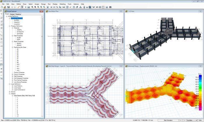
Users can have up to 4 simultaneous display windows open.
Modeling
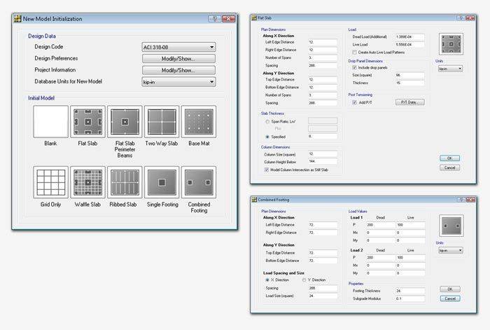
Templates
SAFE offers a variety of templates for quickly starting a new model including flat slabs, two-way slabs, basemats, waffle slabs, ribbed slabs, and single or combined footings.
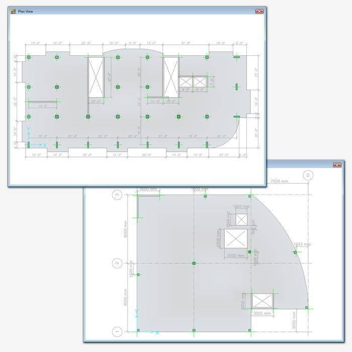
Model Views
View and manipulate analytical model with great precision.
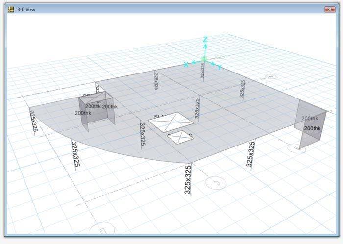
Analytical model views display the finite element model of the structure which is made up of the the connectivity of the joints, frames, shells, and defined meshing.
Drawing Tools
Many drawing and drafting utilities are built into SAFE to enhance the engineer’s modeling experience. Users will find that many of the common industry standard shortcuts and controls are also available in SAFE.
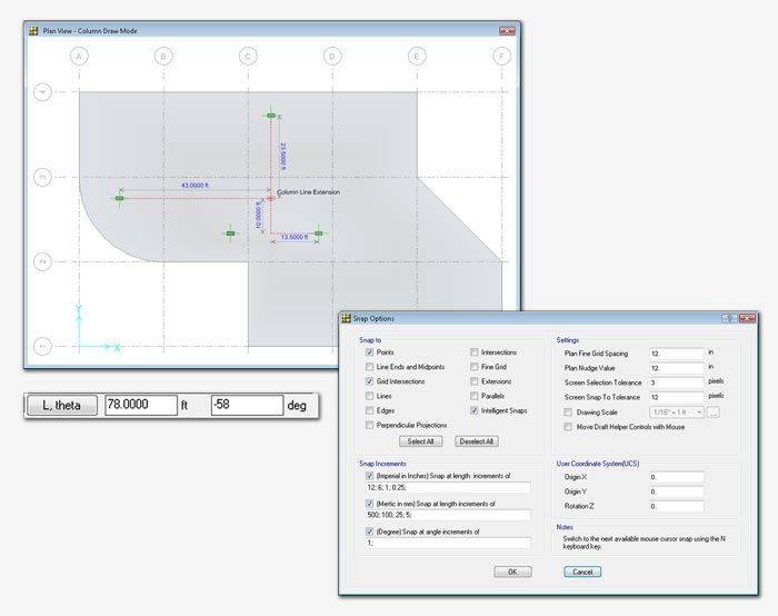
Intelligent snaps make model generation simple by automatically detecting intersections, extensions, parallels, and perpendiculars. Drawing helper tools will show physical extrusions even when in analytical draw mode.
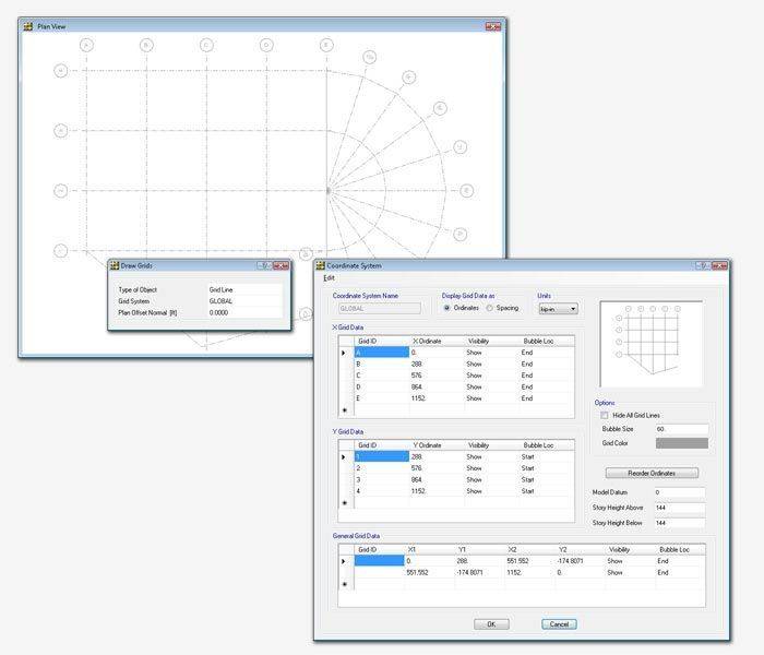
Grid Systems
In SAFE, grids can be defined as cartesian, cylindrical, or general free-form grid systems. There is no limit to the number of grid systems in a model and they can be rotated in any direction or placed at any origin within the model.
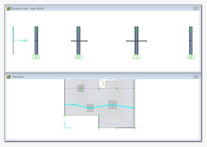
Developed Elevations
Developed elevations can elevate any drawn path on a plan view. This is particularly useful for elevating a path along a design strip.
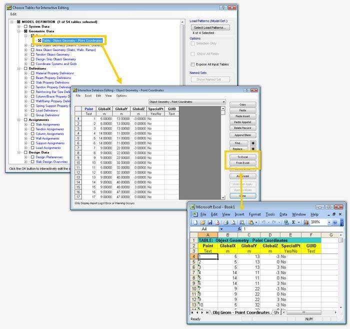
Interactive Database Editing
Interactive database editing allows users to edit model data from a table view which simplifies the task of making changes to the model. Tables are easily exportable and importable from Excel and Microsoft Access.
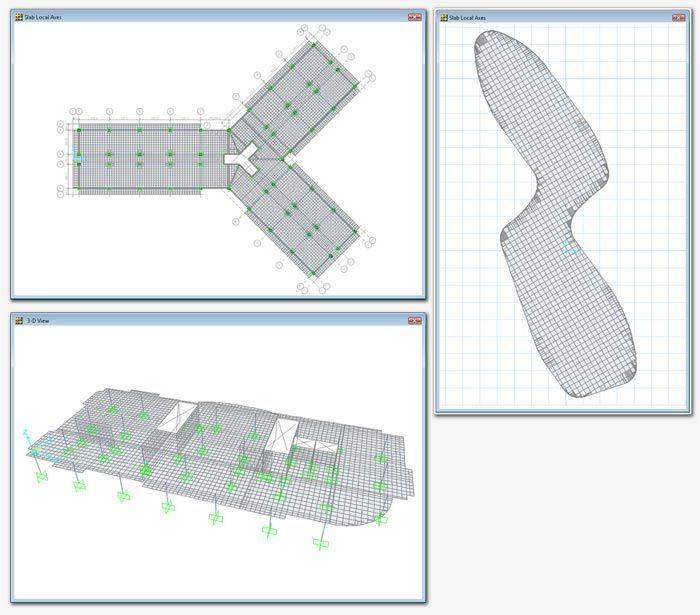
Object Based Meshing
Object based meshing generates meshes based on the specified maximum element size. It will mesh parallel and perpendicular to the longest edge, grid system, or area local axes and will aim to maintain good element aspect ratios.
Dimension Lines
Dimension lines can be drawn on the SAFE model in both architectural or decimal units. They are linked to the objects that they are referencing so if the size of the object changes, so will the dimension line.
Structural Components
Foundations, Basemats, and Footings
SAFE is ideal for modeling foundations, basemats, and footings. Easily model soil supports and zero tension soil models with uplift analysis. The area assignment of soil supports is based on the subgrade modulus, and they automatically adjust whenever the mesh changes. Basemat foundation models can include pedestals, walls, columns, beams, and piles in addition to the foundation area.
Walls and Ramps
Wall and ramps can be modeled as line loads, line supports, or explicitly modeled with wall elements. Define ridge zones to prevent slab deformations at the wall or ramp location.
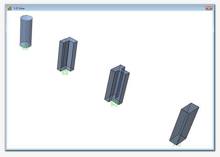
Columns
Columns in SAFE can be Rectangular, T-shaped, L-shaped, Circular, or General with user-defined properties. Rigid zones can be defined to prevent slab deformations at column locations. Drop panels can be easily added at column capitals.
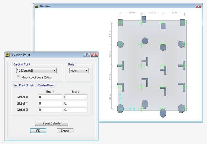
Insertion Points
Insertion points are used to define offsets for beams and columns. They can either be defined on quick SAFE defined cardinal points or based on user-defined dimensions.
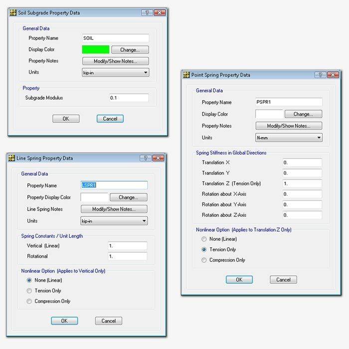
Spring Supports
Spring supports are used to define soil supports. They can be defined as either points, lines, or areas and as tension only or compression only.
Design Strips
Design strips are used to define how reinforcement requirements are to be calculated. SAFE can automatically define the strips for you, or you can define them yourself.
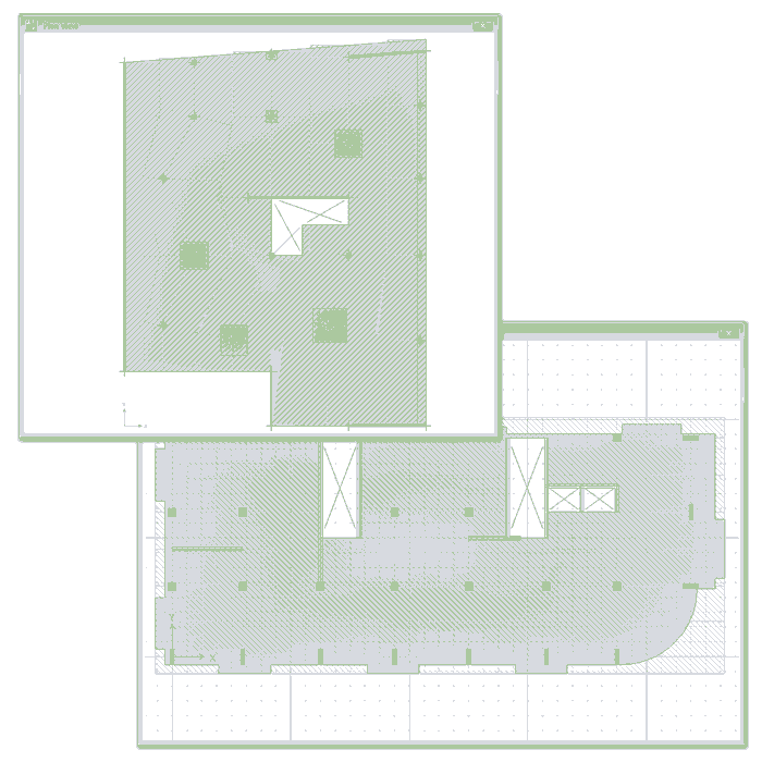
Orthogonal, non-orthogonal, multi-segment, and varying width design strips are all supported supported by SAFE.
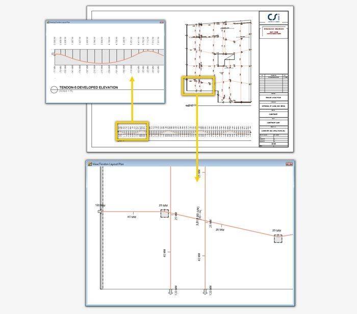
Post-Tensioning (P/T)
SAFE includes the ability to define post-tensioning in slabs, as banded or distributed tendons.
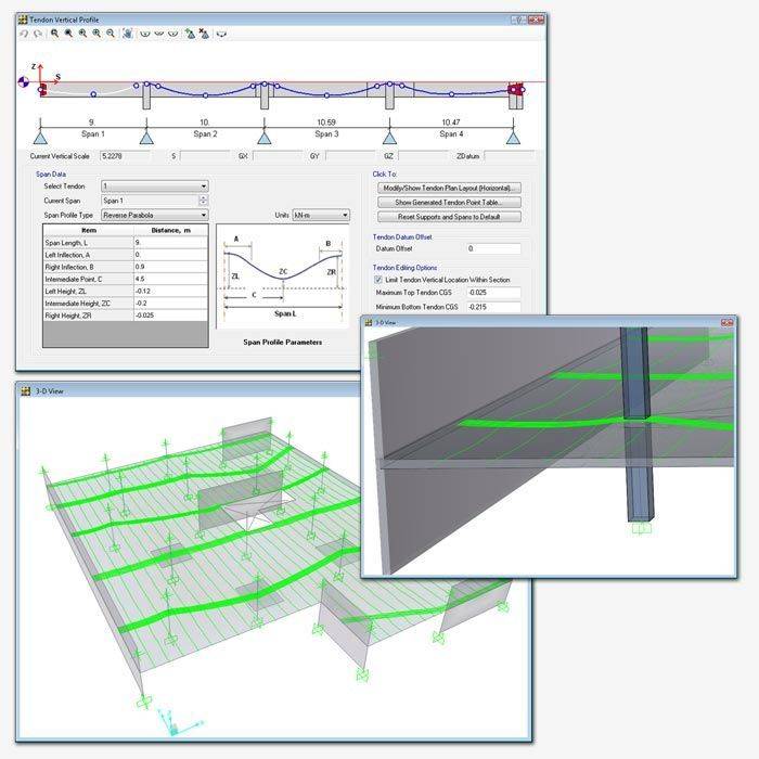
An interactive tendon editor simplifies the task of laying out the tendon profiles. Tendon layouts can also be automated based on strip position and direction.
Loading
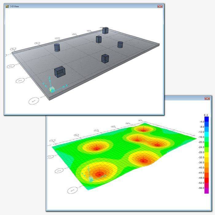
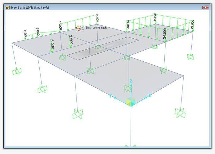
Loading Diagrams
Show the the loads in both 2D and 3D views of your SAFE model. Display color contoured area loading diagrams with loading values, or mouse over various parts of your model to get instantaneous loading values.
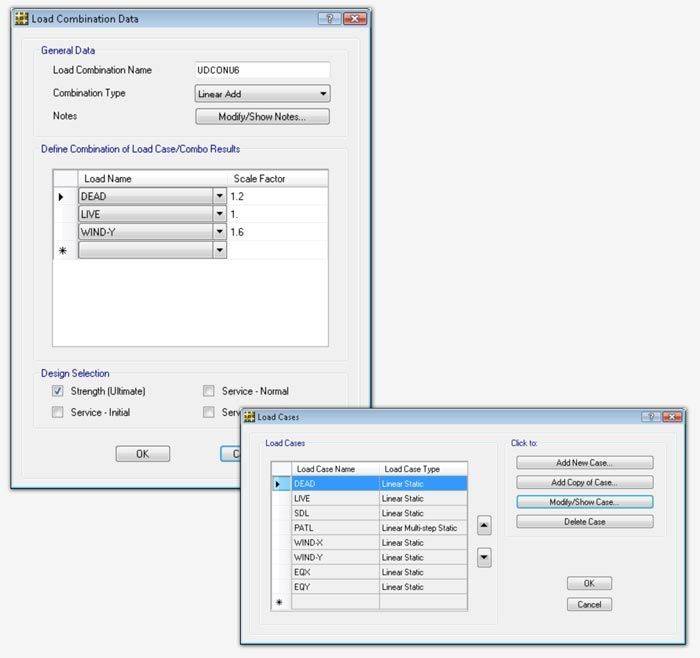
Load Cases and Combinations
SAFE allows for an unlimited number of load cases and combinations. Design combinations will automatically be added based on the selected design code, including strength and service combinations. Linear additive, envelope, absolute additive, SRSS, and range functions have been built in to the load combination editor for efficiency.
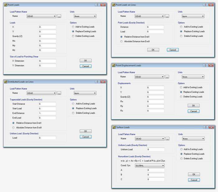
Point, Line, and Area Loads
Point loads can be defined as single points or point loads on lines or areas. Point loads include a load size for punching shear. Line loads can be defined as uniform or trapezoidal. Area loads can be defined as uniform or non uniform surface loads.
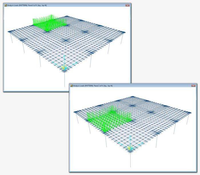
Auto Pattern Live Loads
Auto pattern live loads are automatically generated patterns based on the grids defined by design strips. Results from each “single panel” are combined with the Range Add load combination. User-defined pattern live loads can also be included.
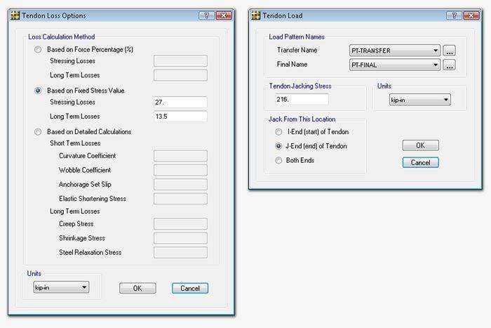
Tendon Loads and Losses
Tendon loads and losses are easily defined and calculated by SAFE. Users can define jacking from either end of the tendon or both. The specified jacking stress is converted to load. Calculation of losses can based on a force percentage, user-defined stress values, or on more detailed calculations.
Analysis
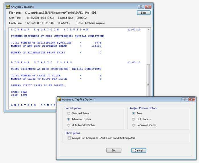
Overview
CSI solvers have been tried and tested by the industry for over 35 years. The SAPFire Analysis Engine can support multiple 64-bit solvers for analysis optimization and perform both Eigen Analysis and Ritz Analysis.
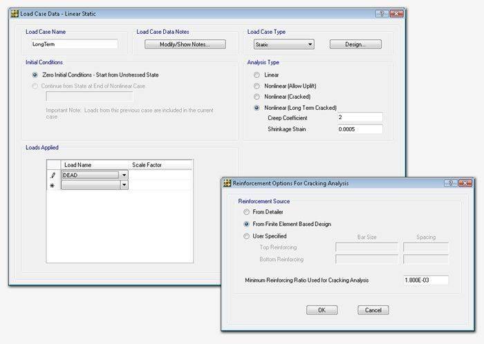
Deflection Control
Deflection control can be performed using a nonlinear analysis or a long-term cracked analysis which takes in to account concrete creep and shrinkage.
Dynamics
Dynamic analyses can be performed using either Ritz or Eigen Vectors. Response spectrum loads and modes can be directly imported from ETABS.
Output and Display
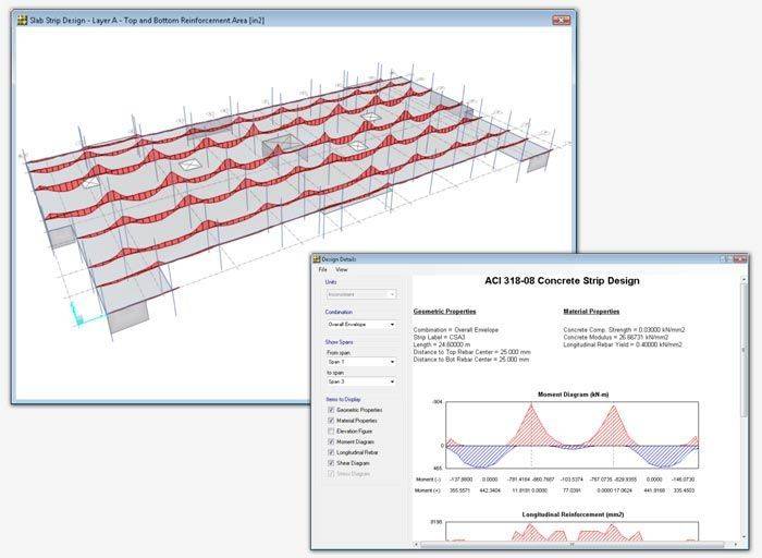
Strip Based Design
SAFE will calculate the minimum reinforcement requirements of area, intensity, or number of bars. Design will be performed at multiple stations. Design strips can be non-orthogonal and of varying width.
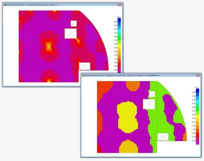
FEM Based Slab Design
Finite element based design does not require design strips. It is ideal for complex geometry where defining strips can be difficult. The design will output contour plots of rebar density by averaging of peaks over user defined widths. This helps with identifying “hot spots” for reinforcing design.
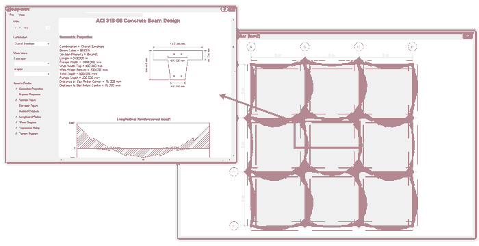
Beam Design
SAFE performs design of conventional and post-tensioned concrete beams per code minimum reinforcement requirements. Flexure, shear, and torsion are all considered in design.
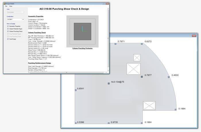
Punching Shear Check
The punching shear check and design in SAFE considers column location, openings, and slab edges. SAFE will also perform an additional drop panel check and design punching reinforcement ties or shear studs if required.
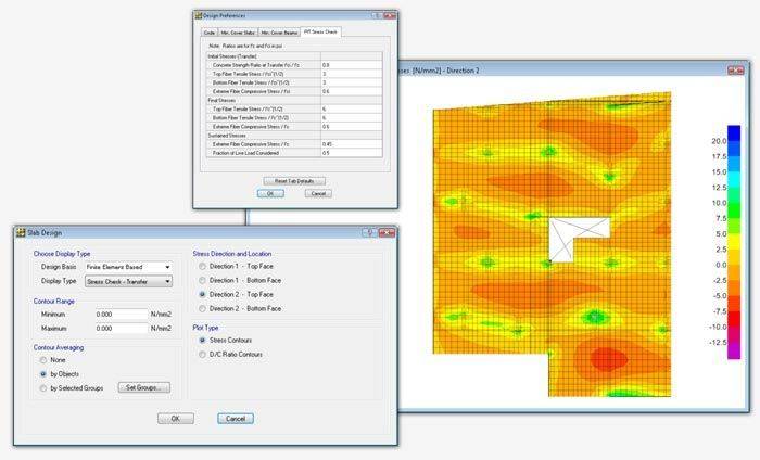
Post-Tensioning Stress Checks
Post-tensioning stress checks are performed for transfer, final, and long term conditions. SAFE will display top/bottom of slab stress contours as well as demand capacity ratio contours that users can mouse over for instantaneous values.
Design Codes
SAFE will peform both traditional reinforced concrete design checks as well as post-tensioned concrete design.

Παρουσίαση Αποτελεσμάτων
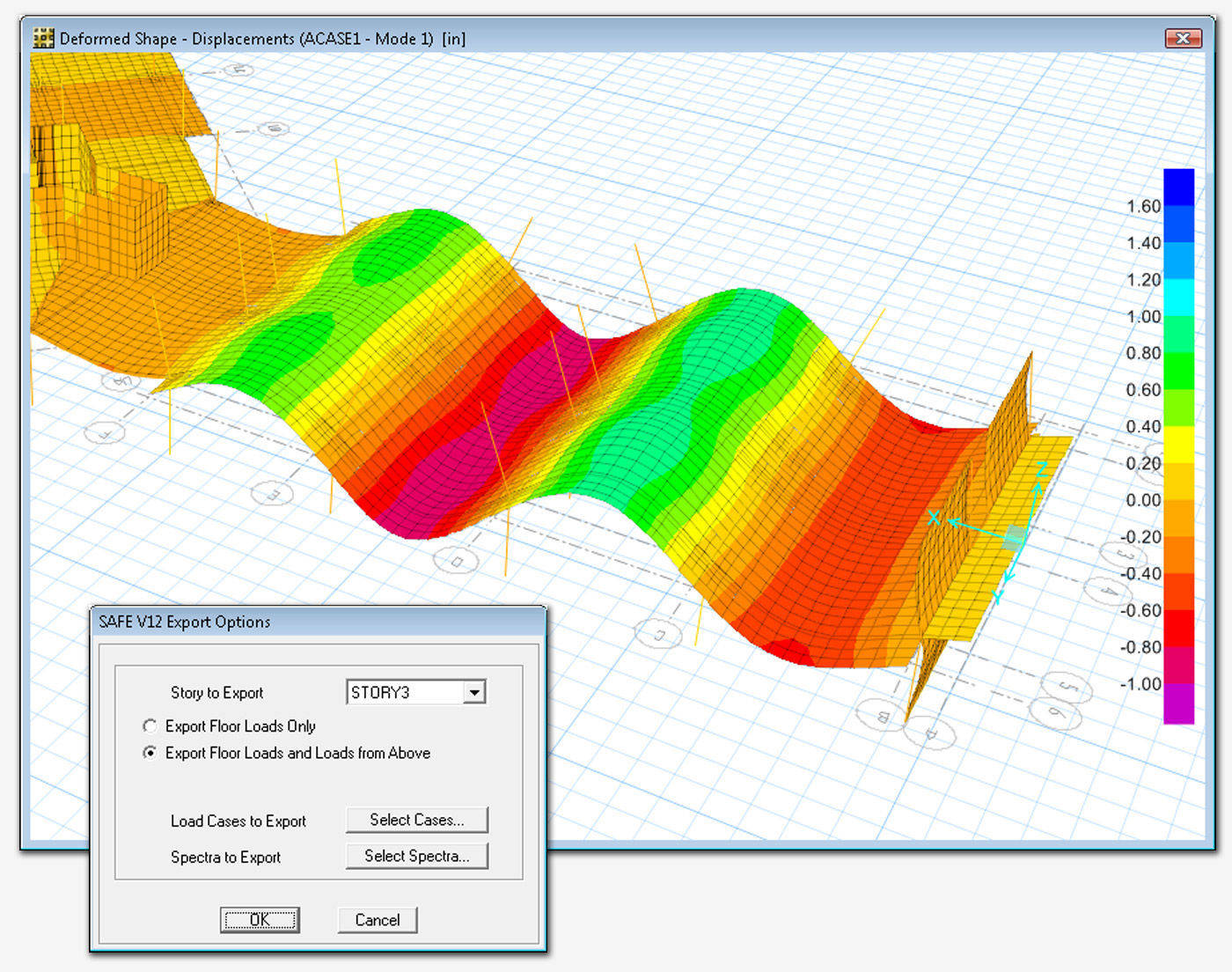
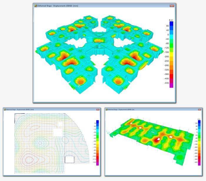
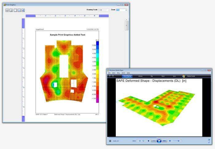
Deformed Geometry
Deformed geometry can be shown after running the analysis. Values are displayed instantaneously when you mouse over the model. The deformed geometry can be displayed as filled or line contour plots.
Force Diagrams
Display axial force, shear, moment, torsion, and stress diagrams on beams or strips for individual load cases or combinations in both 2D and 3D views. Minimum and maximum values will automatically be displayed.
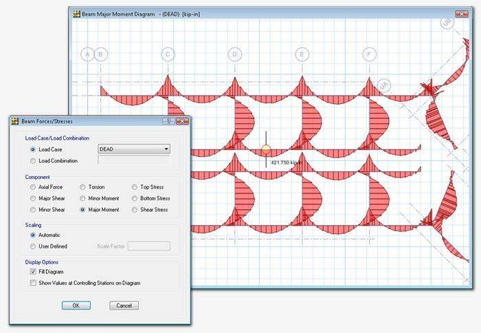
Force diagrams can be displayed for any component.
Shell Contours
Display force, moment, shear, and stress contour plots based on a particular load case or load combination in both 2D or 3D views.
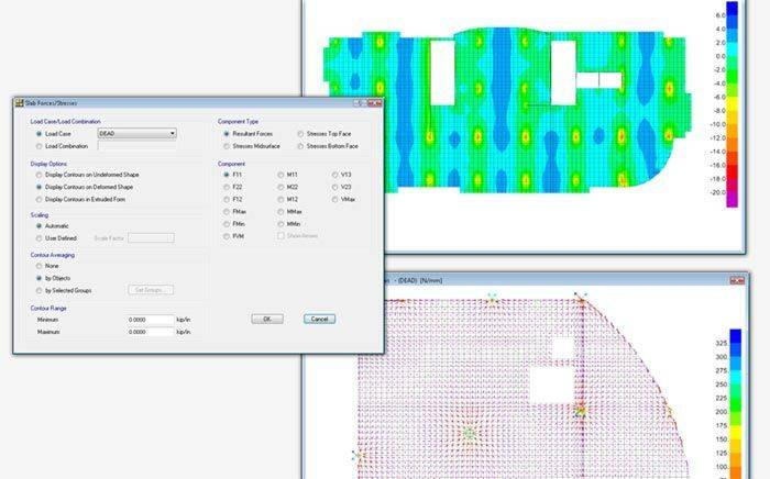
Display shell contours as load flow arrows or as stress contour plots.
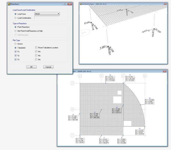
Reaction Diagrams
Display selected reaction components for load cases and combinations as vectors and values, or as tables that can be positioned by the user.
Animations and Image Capture
Make your work shine by capturing images as EMF, BMP, JPG, TIF, GIF, or PNG and include them in your client reports. SAFE also performs video capture of animations as AVI files.
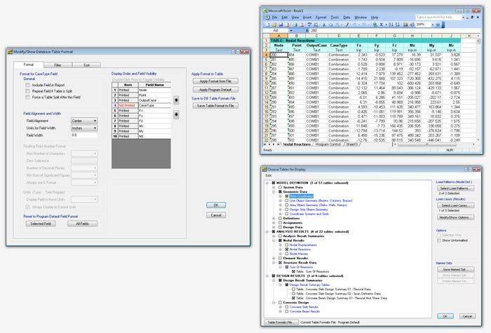
Tabular Output
View database tables containing all input data, analysis results, and design results in a tabular format within the SAFE user interface. Users can filter, sort, and query the table data and print or save the data to Microsoft Access, Excel, HTML, or Text formats.
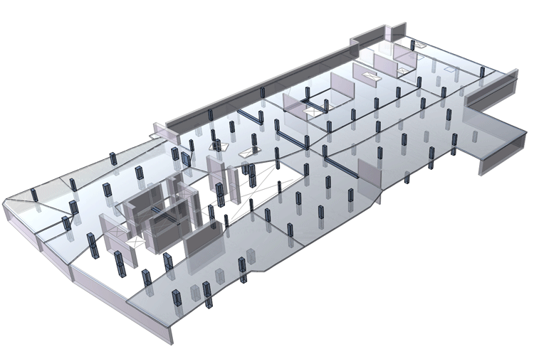
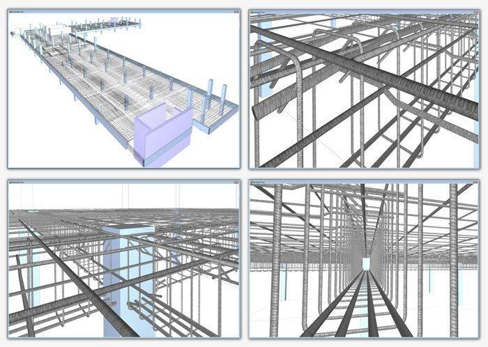
Rendered Views
Display and capture realistic model views, including rebar cages, in a 3D view that is based on the SAFE detailing rebar layouts.
Detailing
Drawing Generation
SAFE will detail your concrete slab based on the design results. Specify detailing rules and choose from standard, metric, and ANSI sheet size and engineering, metric, and architectural scales.
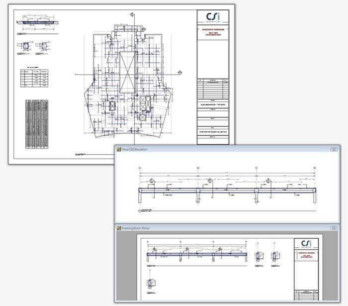
Typical drawing sheets automatically generated and are composed of drawing component views. Add views from the component list or by drag-and-drop directly from from the Model Explorer onto the drawing sheets.
Component Views
Drawing component views are the basic building blocks for drawings. Drag framing plans, reinforcement plans, section cuts, rebar tables and schedules, bill of quantities, reinforcement profiles, tendon layout plan, and tendon profile elevations onto sheets to create your drawings.
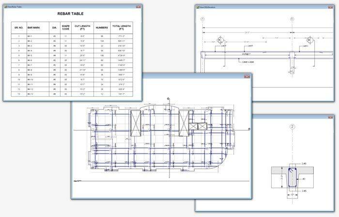
Reinforcement Plans
SAFE detailing will display all reinforcement plans to show indicative bars or all bars.
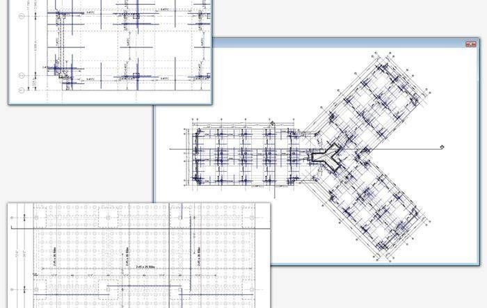
Users can customize rebar callouts or bar marks. Reinforcement will always follow strip directions.
Tendon Layout Plans
Detailing of tendons in SAFE will show all tendons or indicative tendons, anchor and stressing end indicators, and tendon profile elevations.
Section Cuts
Get an instant section cut elevation by defining sections and ranges through slabs, beams, and mats.
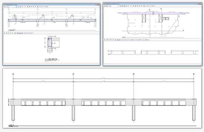
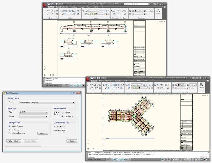
Print and Export Drawings
Print drawings and views directly to a printer or plotter. Alternatively, export drawings and views to DXF or DWG format and edit drawings further in AutoCAD or other CAD software.
Reporting
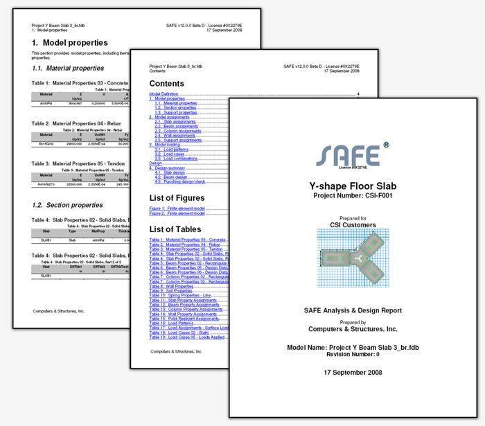
Report Generation
The report generator features include an indexed table of contents, model definition information, and analysis and design results in tabulated format. The report generation is fully customizable to include only the content that you want.
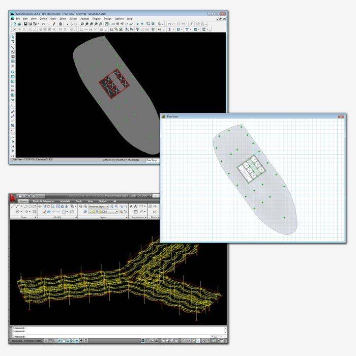
Import and Export
Supported Formats
Import models from SAP2000 and ETABS. All loads, geometry, section properties, and wall deformations can be imported. Import and export geometry and result plots from DXF or DWG files. SAFE is also compatible with Autodesk Revit Structure.
ACE-Hellas S.A.
Integrated Solutions