BUILDING ANALYSIS AND DESIGN
Description
| Knowledge Base | |
|
|
|
| ETABS Releases | |
|
|
|
| ETABS 21.0.0 | 21.0.1 Enhacements | Release Notes
LEARN ABOUT THE NEW FEATURES IN THE LATEST RELEASE |
|
|
|
|
The innovative and revolutionary new ETABS is the ultimate integrated software package for the structural analysis and design of buildings. Incorporating 40 years of continuous research and development, this latest ETABS offers unmatched 3D object based modeling and visualization tools, blazingly fast linear and nonlinear analytical power, sophisticated and comprehensive design capabilities for a wide-range of materials, and insightful graphic displays, reports, and schematic drawings that allow users to quickly and easily decipher and understand analysis and design results.
From the start of design conception through the production of schematic drawings, ETABS integrates every aspect of the engineering design process. Creation of models has never been easier – intuitive drawing commands allow for the rapid generation of floor and elevation framing. CAD drawings can be converted directly into ETABS models or used as templates onto which ETABS objects may be overlaid. The state-of-the-art SAPFire 64-bit solver allows extremely large and complex models to be rapidly analyzed, and supports nonlinear modeling techniques such as construction sequencing and time effects (e.g., creep and shrinkage).
User Interface
One Window, Many Views
ETABS offers a single user interface to perform: Modeling, Analysis, Design, Detailing, and Reporting. A new model explorer is available for quick access to objects, properties, and forms.
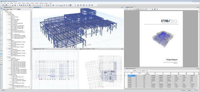
Users now have no limit on the the number of model windows and views for model manipulation and data views.
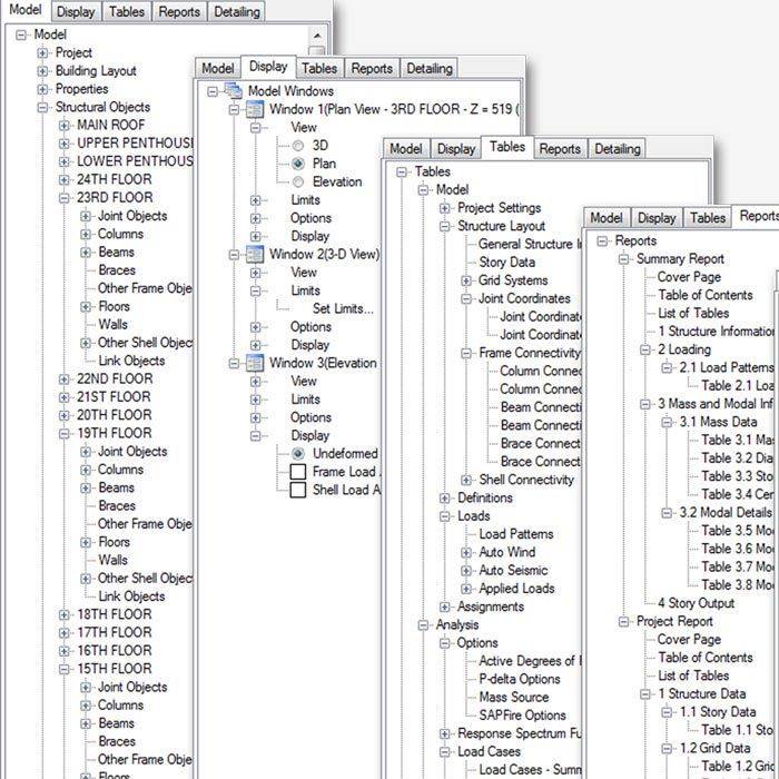
The ETABS model explorer greatly enhances the user’s ability to manage the data in their model. Users can define, duplicate, and modify properties in groups. Drag and drop properties right onto the models for assignment. User defined displays can be easily setup in the model explorer to for quick navigation.
Hardware Accelerated Graphics
Direct X graphics with hardware accelerated graphics allow for navigation of models with fly-throughs and fast rotations.
Modeling
Templates
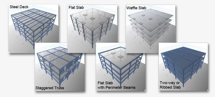
ETABS has a wide selection of templates for quickly starting a new model. At this model template stage, the user has the ability to define grid and grid spacing, the number of stories, the default structural system sections, default slab and drop panel sections, and uniform loads (specifically dead and live loads).
Model Views
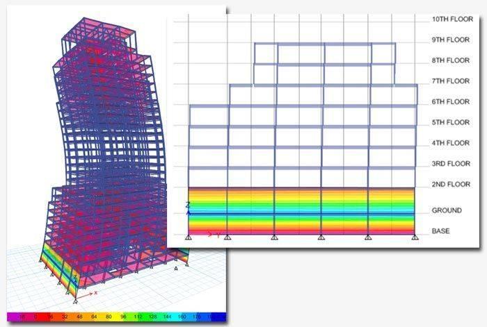
View and manipulate analytical model with great precision. Plans and Elevation views automatically generated at every grid line. Easily define custom views and cutting planes to view and manipulate complex geometry with ease.
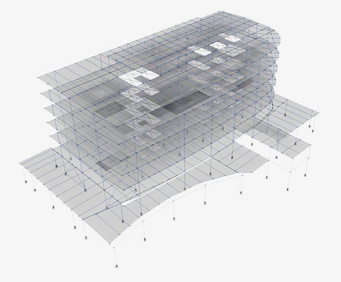
Analytical model views display the finite element model of the structure which is made up of the the connectivity of the joints, frames, and shells and defined meshing.
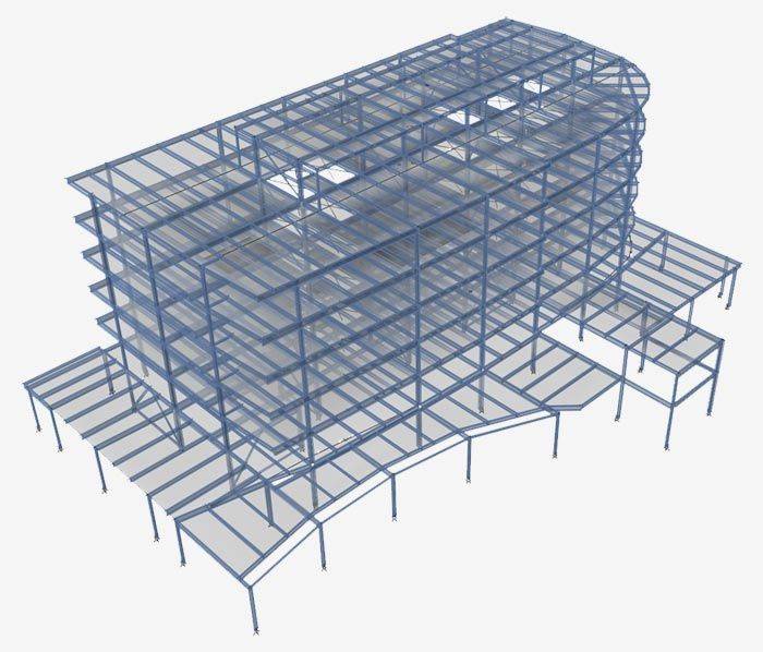
Physical model views accurately display cardinal insertion points, local axes rotations, wall junctions, and geometry.
Grid Systems
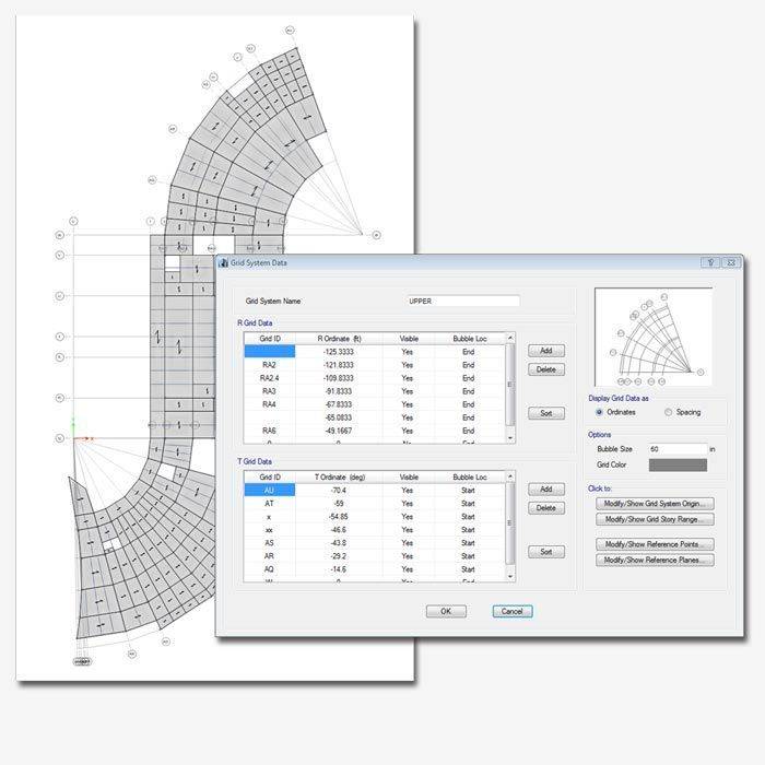
In ETABS, grids can be defined as cartesian, cylindrical, or general free-form grid systems. There is no limit to the number of grid systems in a model, and they can be rotated in any direction or placed at any origin within the model.
Drawing Tools
Many drawing and drafting utilities are built into ETABS to enhance the engineer’s modeling experience. Users will find that many of the common industry standard shortcuts and controls are also available in ETABS.
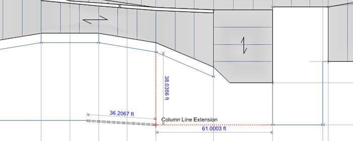
Intelligent snaps make model generation simple by automatically detecting intersections, extensions, parallels, and perpendiculars. Drawing helper tools will show physical extrusions even when in analytical draw mode.
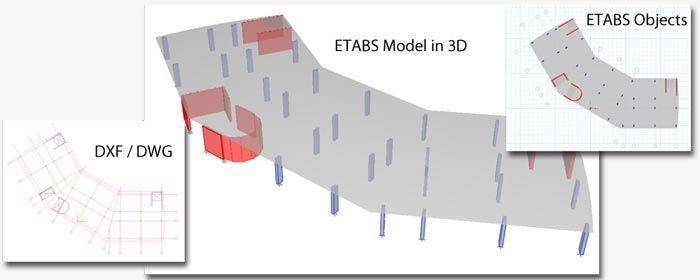
Easily import an architectural DXF/DWG into the background of the ETABS modeling window and use it as a template to trace over to help you create your model. Turn layers on and off to easily pick which layer(s) you want to see. You can also right button click on an element to quickly convert an area into an ETABS structural object.
Plans and Elevations
Plan and elevation views are automatically generated at every grid line to allow for quick navigation of the model. Users can create their own elevation sections by using our Developed Elevation feature.
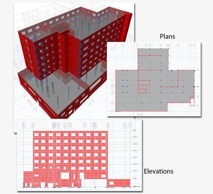
When in a 2D view, see arrow buttons to quickly move from grid line by grid line. A transparent plane will be show in the 3D view to show you exactly which elevation or plane you are looking at in the model.
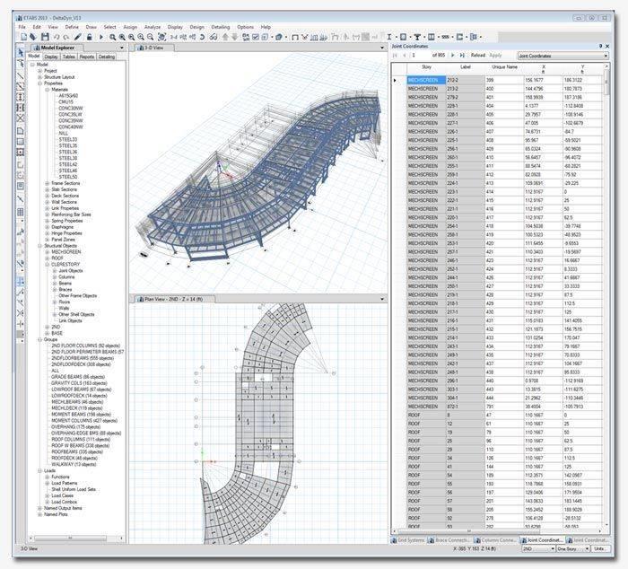
Interactive Table Data Editing
ETABS data can be viewed and edited using on-screen dockable tables. This is quite useful for defining a model from spreadsheets or viewing analysis or design results.
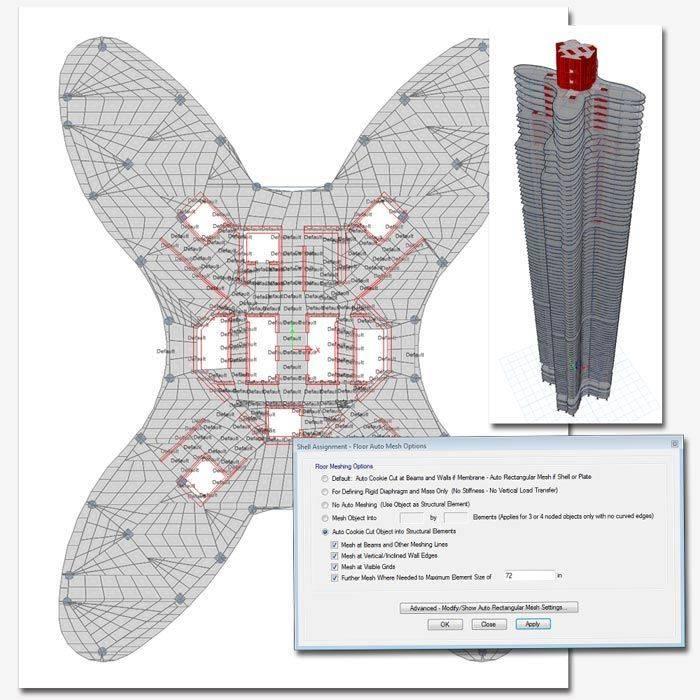
Meshing Tools
Engineers have many options when it comes to mesh generation in ETABS. Simply select the area object and then select the rules for the automatic mesh generator to use.
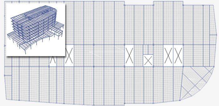
Object meshing is automated based on maximum element size. The mesh will always be parallel and perpendicular to longest edge, grid system, or area local axes and aims to maintain good element aspect ratios.
Users also have the option to manually mesh objects into the model. This is referred to as external meshing. The results in a one-to-one correspondence between object and elements.
The Automatic Edge Constraint is an internal algorithm that will address the issue of mismatched meshes. For example, if the nodes of a ramp and a wall do not match up, ETABS will internally connect all mismatched meshes using a special joint interpolation algorithm to act as a “zipper” between the elements.
Building Components
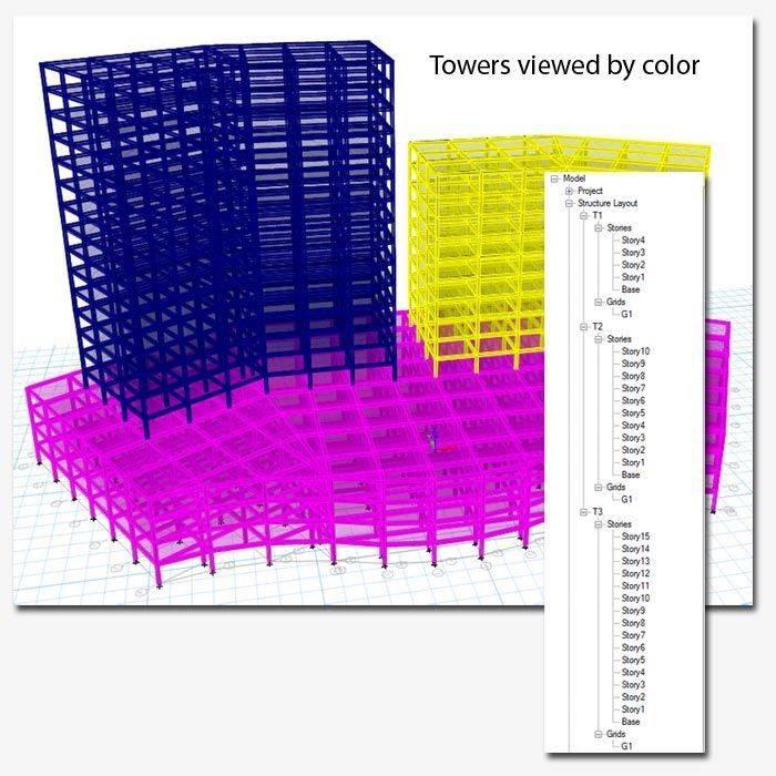
Towers
Multi-tower buildings can now easily be modeled by using the new tower feature. Defining towers in an ETABS model allows users to define unique story levels and grid systems for different building structures within the same ETABS model. For example, ETABS models can share a podium level and then separate into towers on higher floors.
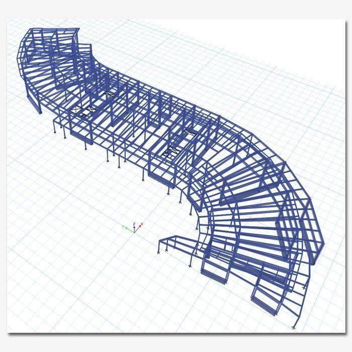
Beams, Columns, Braces
In ETABS, beams, columns, and braces are frame elements that can be straight or curved. They are used in a general, three-dimensional, beam-column formulation which includes the effects of biaxial bending, torsion, axial deformation, and biaxial shear deformations. Intermediate joints will automatically be generated where other members intersect with the frame to ensure finite element connectivity.
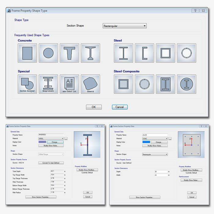
Section Properties
ETABS has a built-in library of standard concrete, steel, and composite section properties of both US and International Standard sections. Even non-prismatic and built up steel sections can be easily defined. Use our Section Designer for more complex sections.
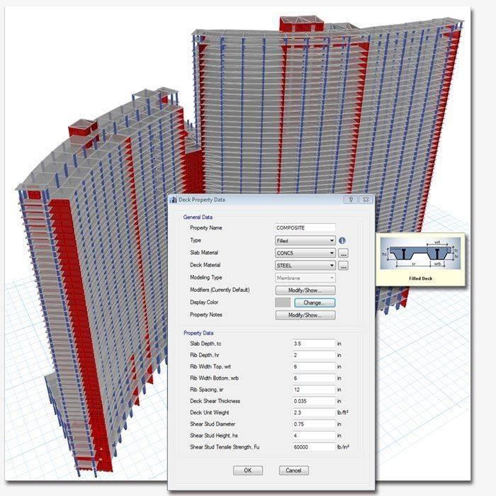
Shells (Walls, Floors, Ramps)
Shell elements are used to model walls, floors, and ramps. A layered shell element has been added in ETABS that considers mixed material composite behavior, as well as nonlinear material behavior options for each layer based on stress-strain, with shearing behavior considered for rebar layered shell sections.
Shear Walls
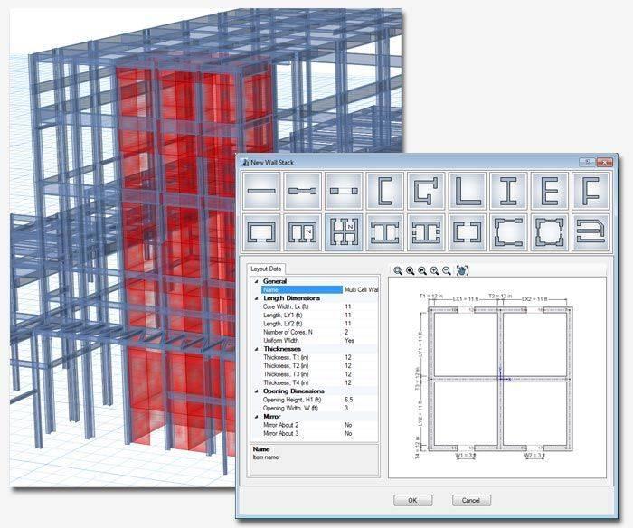
Customizable wall configuration templates help you define your wall section properties with ease by drawing multilevel wall configurations in a single click. When you draw walls using the wall stack, all pier and spandrel labeling is automatically assigned.
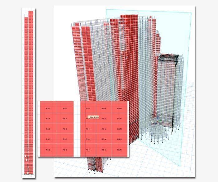
Pier and spandrel labels produce integrated shears and moments for design purposes, for walls modeled with area finite elements. For example, an assemblege of 20X20 meshed shear wall areas could have results displayed and reported as if it were a single column.
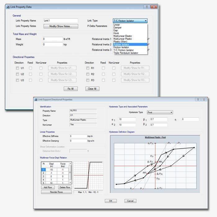
Link Elements
ETABS has a many different link elements available for users to accurately represent the behavior of a structure. Link elements types include Linear, Multi-linear Elastic, Multi-linear Plastic, Gaps, Hooks, Dampers, Friction Isolators, Rubber Isolators, T/C Isolators, and Triple Pendulum Isolators.
Hinge Properties
Users can create and apply hinge properties to perform pushover analyses in ETABS. Nonlinear material behavior in frame elements (beam/column/brace) can be modeled using fiber hinges. Mixed materials, like reinforced concrete, and complex shapes can be represented. Yielding, cracking, and hysteresis behavior can all be captured using hinge properties.

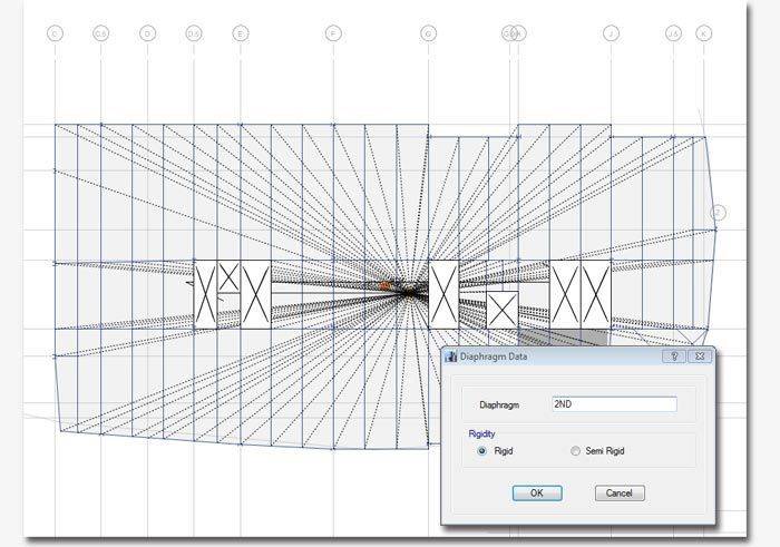
Floor Diaphragms
Rigid, semi-rigid, and flexible floor diaphragms can be defined in ETABS. Diaphragms can be assigned to joint objects or area objects.
Loading
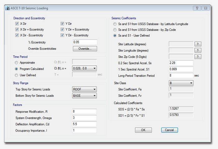
Automated Code Based Loading
ETABS will automatically generate and apply seismic and wind loads based on various domestic and international codes.

Supported codes included in ETABS
- ASCE 7-88
- ASCE 7-95
- ASCE 7-02
- ASCE 7-05
- ASCE 7-10
- AS/NZS 1170.2:2002
- GB50009-2012
- Eurocode 1 2005
- Indian IS875:1987
- Italian NTC 2008
- NBCC 2010
- NBCC 95
- NBCC 2005
- Turkish TS 498-97
- BOCA96
- BS 6399-95
- Mexican
- UBC 94
- UBC 97
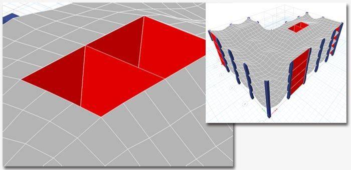
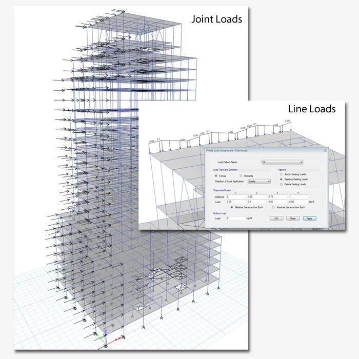
Point, Line, Area, and Thermal Loads
ETABS is robust when it comes to assigned loads. Uniform or non-uniform surface loads can be assigned in any direction, not just gravity. Uniform or trapezoidal loads can be defined on lines in any direction. Thermal load can be assigned to joints, lines, and areas.
Cladding
Automatically add analytical cladding to entire structure for loading purposes.
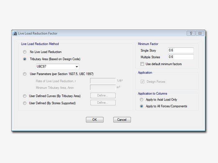
Live Load Reduction
Live-load-reduction factors may be assigned on a member-by-member basis. This may be done either within the graphical user interface, once design is complete, by right-clicking on a member, or it may be done using interactive database editing.
Supported codes and user defined types included in ETABS
- ASCE 7-95
- ASCE 7-05
- ASCE 7-10
- AS/NZ 1170.1-2002
- Chinese GB 50009-2012
- Eurocode 1991:2002
- Hong Kong COP 2011
- IS 875-1987
- NBCC95
- NBCC2005
- NBCC2010
- UBC97
- User Parameters (per Section 1607.5, UBC 1997)
- User Defined Curves (By Tributary Area)
- User Defined (By Stories Supported)
Analysis
Overview
CSI Solvers have been tried and tested by the industry for over 35 years. The SAPFire Analysis Engine can support multiple 64-bit solvers for analysis optimization and perform both Eigen Analysis and Ritz Analysis.
Dynamics
ETABS dynamic analysis capabilities include the calculation of vibration modes using Ritz or Eigen vectors, response-spectrum analysis, and time-history analysis for both linear and nonlinear behavior.
Eigen-vector modal analysis finds the natural vibration modes of the structure, which can be used for understanding the behavior of the structure, and also as the basis for modal superposition in response-spectrum and modal time-history load cases. Ritz-vector modal analysis finds the optimum modes for capturing structural behavior in response-spectrum and modal time-history load cases, and is more efficient for this purpose than Eigen-vector analysis.
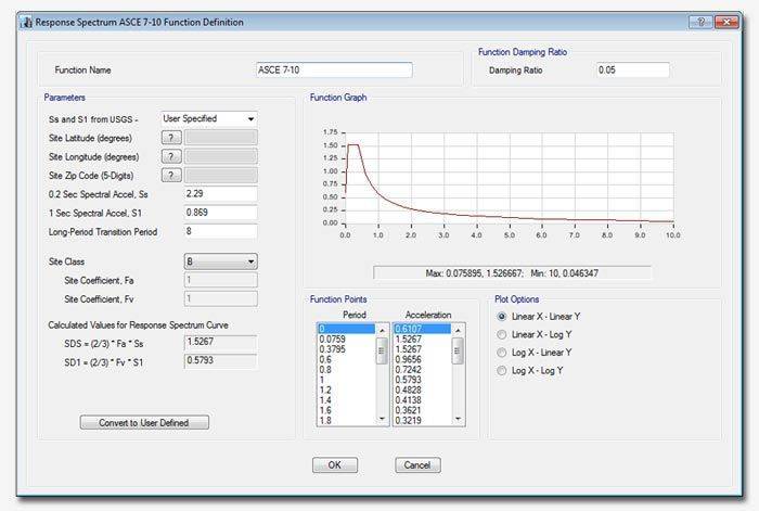
Response-spectrum analysis determines the statistically likely response of a structure to seismic loading. This linear type of analysis uses response-spectrum ground-acceleration records based on the seismic load and site conditions, rather than time-history ground motion records. This method is extremely efficient and takes into account the dynamical behavior of the structure.
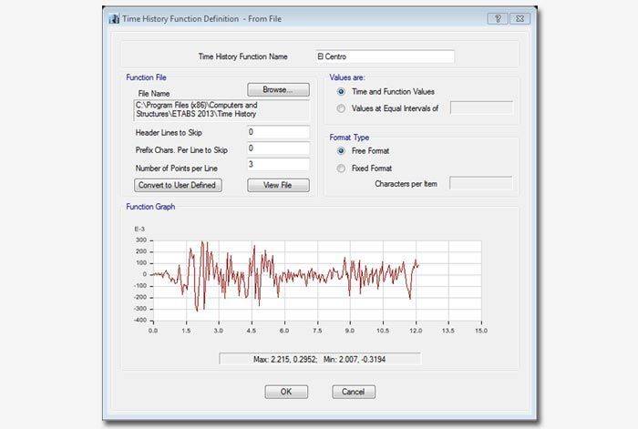
Time-history analysis captures the step-by-step response of structures to seismic ground motion and other types of loading such as blast, machinery, wind, waves, etc. Analysis can use modal superposition or direct-integration methods, and both can be linear or nonlinear. The nonlinear modal method, also called FNA for Fast Nonlinear Analysis, is extremely efficient and accurate for a wide class of problems. The direct-integration method is even more general, and can handle large deformations and other highly nonlinear behavior. Nonlinear time-history analyses can be chained together with other nonlinear cases (including staged construction) addressing a wide range of applications.
P-Delta
P-delta analysis captures the softening effect of compression and the stiffening effect of tension. A single P-delta analysis under gravity and sustained loads can be used to modify the stiffness for linear load cases, which can later be superposed. Alternatively, each combination of loads can be analyzed for full nonlinear P-delta effects. P-delta effects are included for all elements and are seamlessly integrated into analysis and design.
Buckling
Linear (bifurcation) buckling modes of a structure can be found under any set of loads. Buckling can be calculated from a nonlinear or staged-construction state. Full nonlinear buckling analysis is also available considering P-delta or large deflections effects. Snap-through buckling behavior can be captured using static analysis with displacement control. Dynamic analysis can be used for modeling more complex buckling, such as follower-load problems.
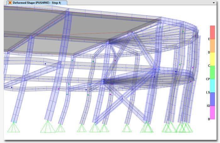
Pushover
Pushover analysis features in ETABS include the implementation of FEMA 356 and the hinge and fiber hinge option based on stress-strain. The nonlinear layered shell element enables users to consider plastic behavior of concrete shear walls, slabs, steel plates, and other area finite elements in the pushover analysis. Force-Deformation relations are defined for steel and concrete hinges.
Time Dependent
Incremental construction sequence modeling and loadings can be modeled in ETABS. Nonlinear effects can be considered such as large deflections, yielding, and gap opening and closing. Time-dependent creep, shrinkage, and strength-change effects will all so be taken into account.
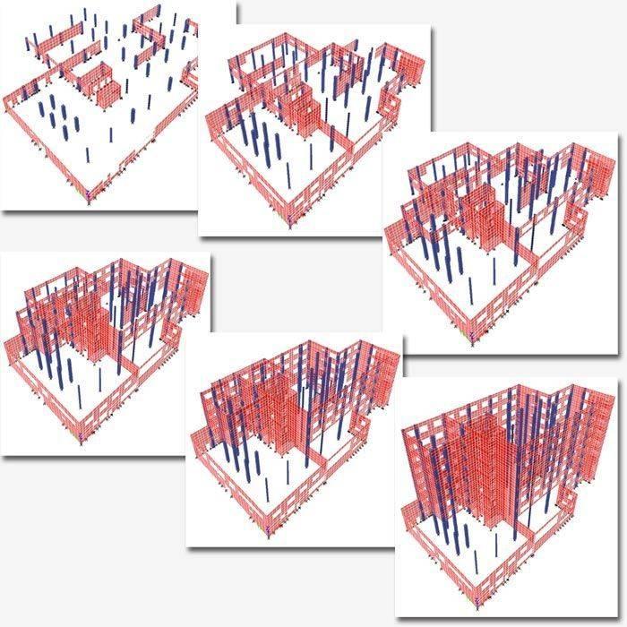
Users can add arbitrary loading sequences at various points to simulate real life construction conditions.
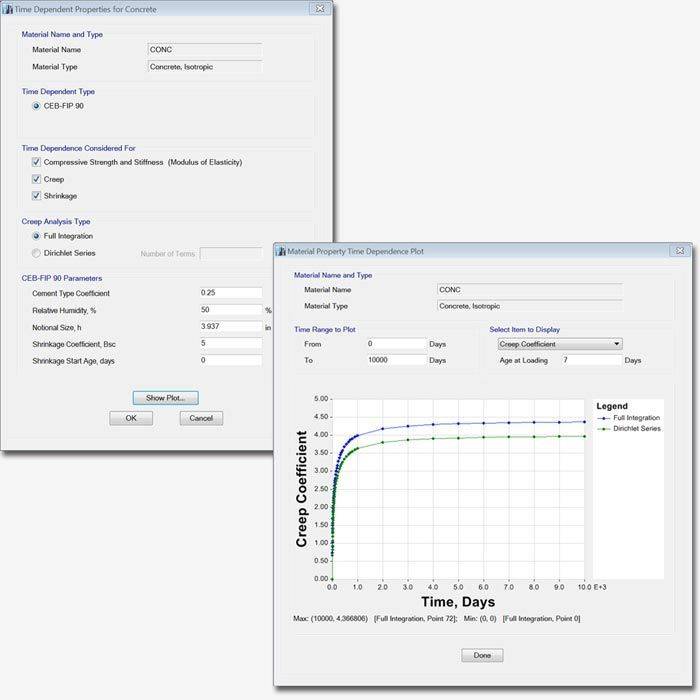
Long term deflections due to creep and shrinkage can be computed along with staged sequential construction analysis. Time dependent material properties are based upon the 1990 edition CEB-FIP code and user defined curves are used to compute creep strains.
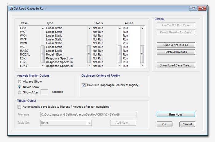
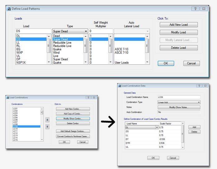
Load Cases and Combinations
ETABS allows for an unlimited number of load cases and combinations. Load combination types include linear additive, envelope (min/max), absolute add, SRSS, and range combinations. Combination components can include other combinations.
Model Alive
For small to medium sized structures, analysis can be performed on the fly as you build and modify the model. For each change you make to the geometry, properties, or loading, the structure instantly responds with the new deformed shape, moment diagram, or any other plot of results. It’s like working with a live model, and it is a very powerful tool for conceptual design and for testing “what-if” scenarios.
Design
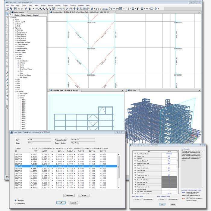
Steel Frame
Fully integrated steel frame design includes member size optimization and implementation of design codes. ETABS allows users to interactively view design results at any frame member, change the parameters or section properties, and display the updated member results.
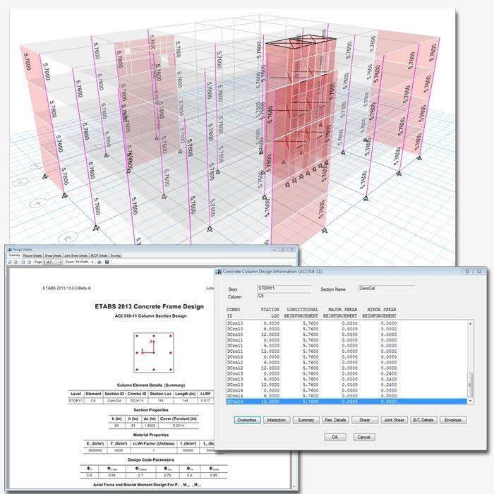
Concrete Frame
Fully integrated concrete frame design in ETABS includes: required area of steel calculations, auto selection lists for new member sizing, implementation of design codes, interactive design and review, and comprehensive overwrite capabilities.
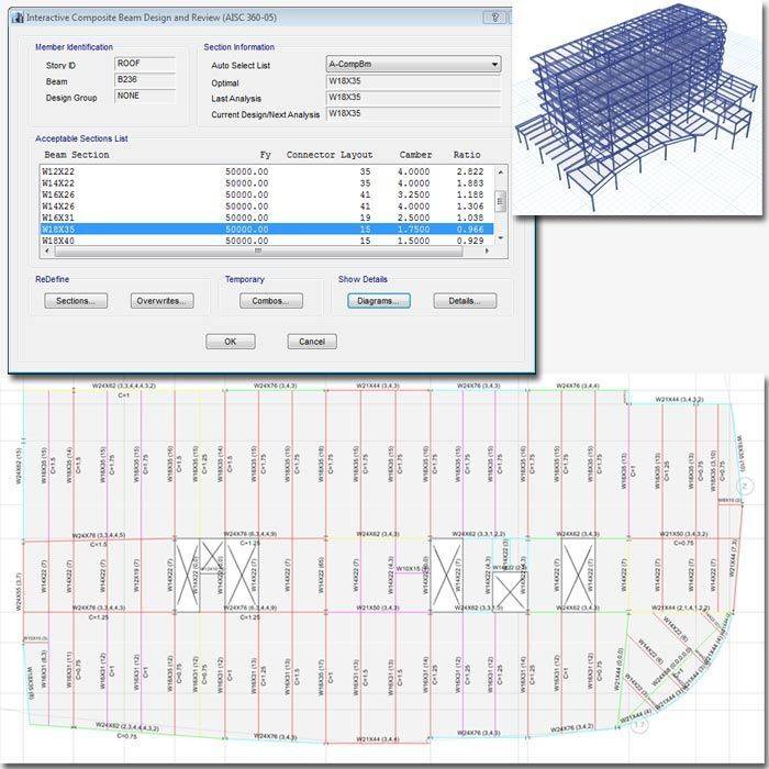
Composite Beam and Column
Fully integrated comprehensive composite beam design includes member sizing using auto-select lists, calculation of camber and stud requirements, implementation of US and many international design codes, and comprehensive overwrite capabilities.
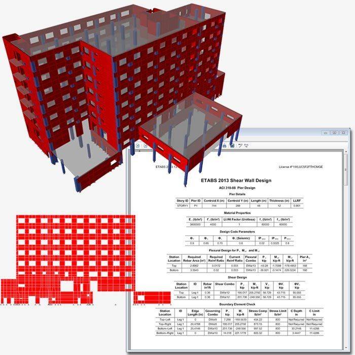
Shear Wall
Fully integrated comprehensive shear wall design includes calculation of reinforcing requirements for both overturning and shear, demand/capacity calculations of defined reinforcement, US and international design codes, and comprehensive overwrite capabilities.
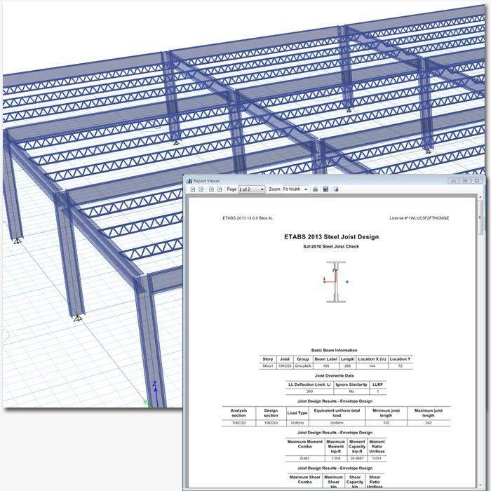
Steel Joist
Fully integrated comprehensive steel joist design includes member sizing using auto-select lists, and overwrite capabilities.
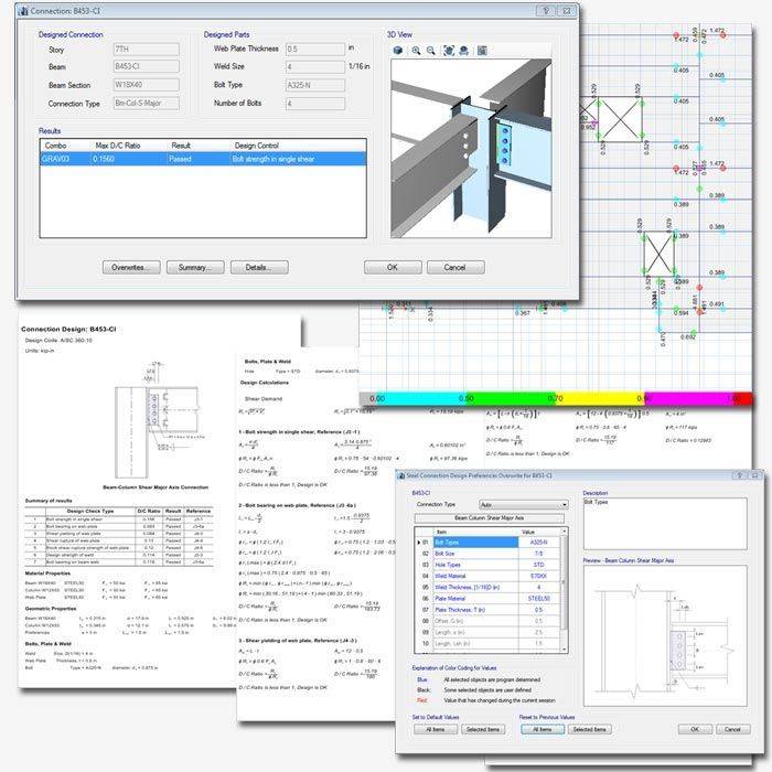
Steel Connection and Base Plate
ETABS uses forces at joints and design preferences to determine connection design in terms of D/C ratio for each load combination. Design is based on load combinations for each design code supported, as well as a set of user-specified loading combinations.
Output and Display
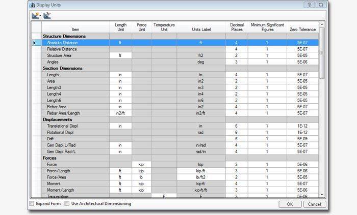
Mixed Units
ETABS gives users full control of the units used with all model data and displays results in the units desired. Whether architectural units or analysis results units, you can have any combination of units throughout your model.
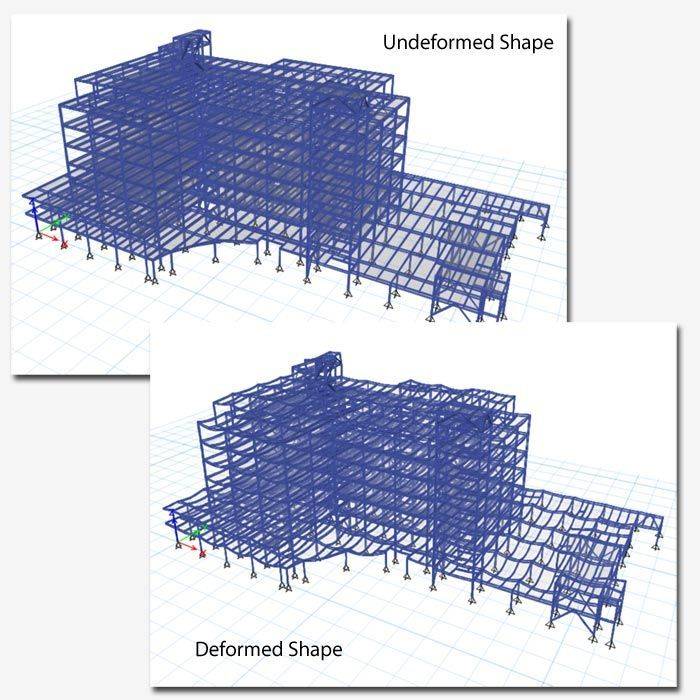
Deformed Geometry
Users can display deformed geometry based on any load or combination of loads, as well as animations of modes.
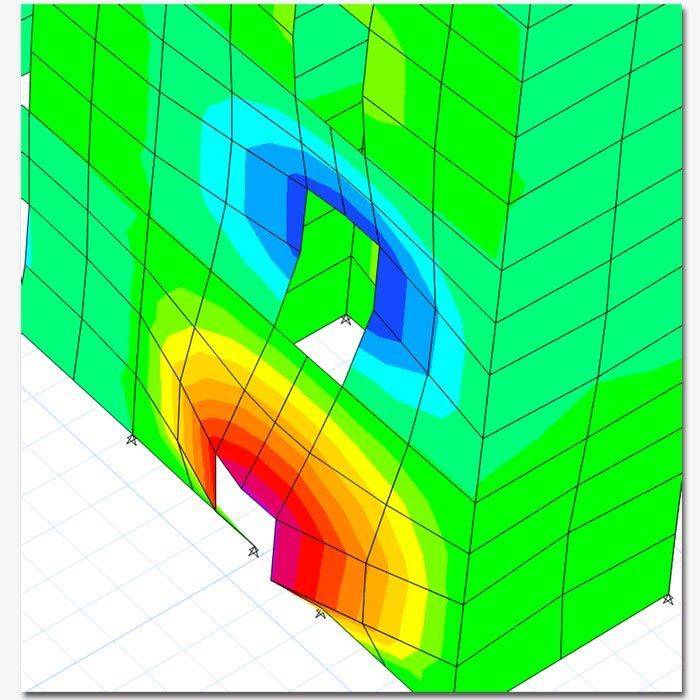
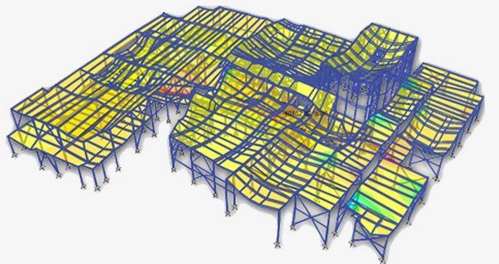
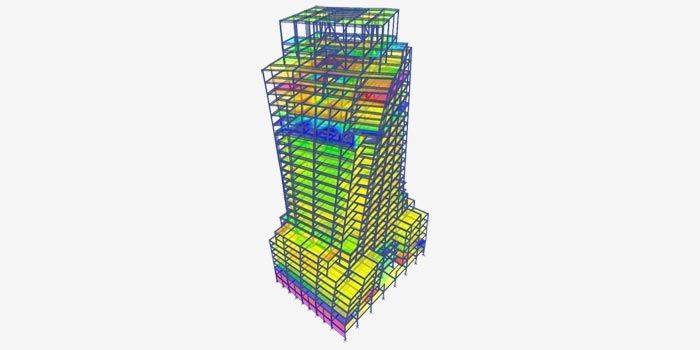
Shell Force and Stress Contours
Display of shell forces and stress contours can be based on load case, load combination, or modal case. Users can show resultant forces and shell stresses on any component in any direction. Control the stress contour appearance by showing undeformed, deformed, or extruded shapes, with or without loading values.
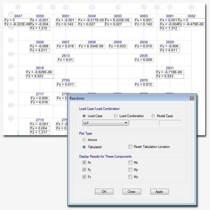
Reaction Diagrams
Support reactions can be displayed graphically on the model either as vectors or as tabular plots for selected reaction components.
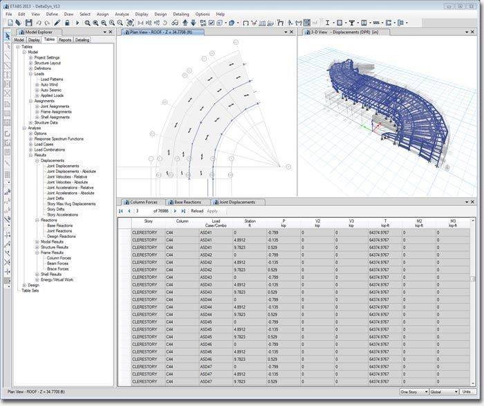
Tabular Output
ETABS has the ability to display and dock tables for all input data, analysis results, and design results. Organize the tables in any way you like by dragging and dropping them to any location of the ETABS environment. Tables support sort, cut, copy, and paste for use in other programs. Print or save tabular data to Access, Excel, Word, HTML, or TXT.
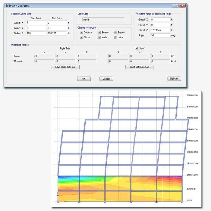
Section Cuts
Use graphical section cut definitions to see the resultant forces and moments across any location in the structure. A section cut can have any shape and can be used to compute story shears, connecting forces, design forces in shear walls, and for many other purposes. Section cut results can be obtained for all types of load cases and combinations.
Video Animations
ETABS has the ability to generate video (.avi) files to visually display a set of analysis results that vary over a particular time period, such as in a time history analysis.
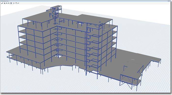
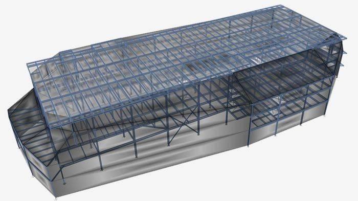
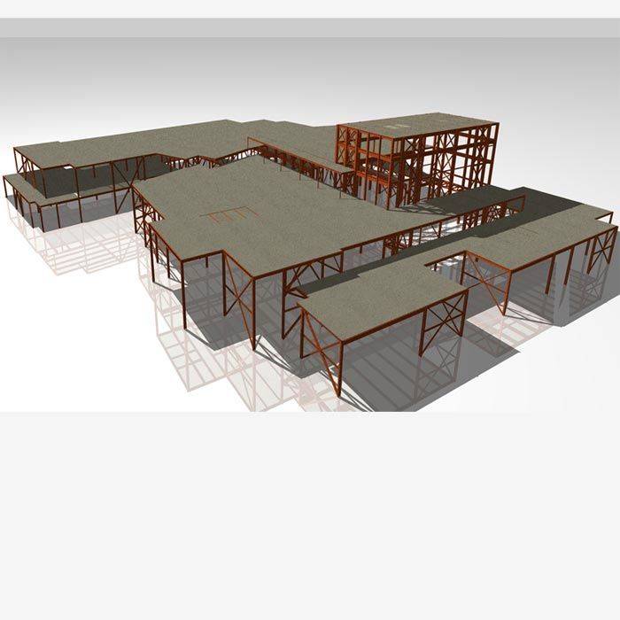
Rendered Views
Rendered views can used to create images to include in client reports. ETABS has multiple lighting options, shadows, and texture options to create life-like images of your structures.
Detailing
Drawing Generation
ETABS has complete drawing generation capabilities incorporated into all levels. The detailing window is like any other ETABS model window.
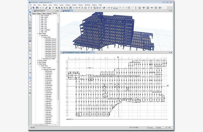
Components views are the basic building blocks for drawings that can be dragged and dropped onto drawing sheets. Detailing components include: concrete beams, columns and walls, steel framing, beam schedules, column schedules, and connections.
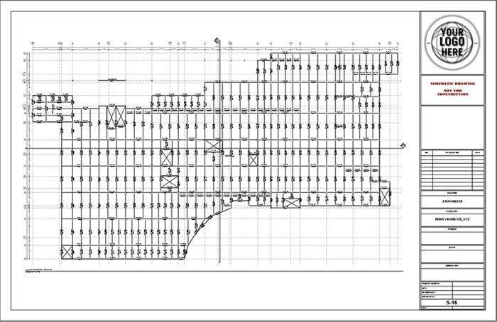
Typical drawing sheets that are automatically generated are composed of drawing component views. Users can add additional drawing views to sheets by dragging and dropping from the Model Explorer. Drawings will synchronize with updates made to the model and reinforcement.

Drawings sheets generated by ETABS support standard, metric, and ANSI sheet sizes. Users can choose from three predefined title blocks, or alternatively users can import their own title block in DXF format. ETABS also supports engineering, metric, and architectural scales in its generated drawings. Full control is given to the user to scale each view on a drawing.

ETABS gives users full control over how drawings are generated. Users can control bar sizes and spacing, set up beam and slab curtailment rules, control information displayed in rebar callouts, specify bars around openings, detail all bars or only those above a typical quantity.
Component Views
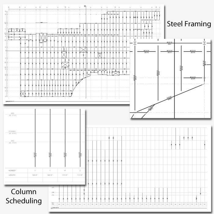
ETABS will perform comprehensive steel detailing and scheduling for floor framing, beams, columns, and connections. Users can control detailing preferences for each type of steel detailing component.
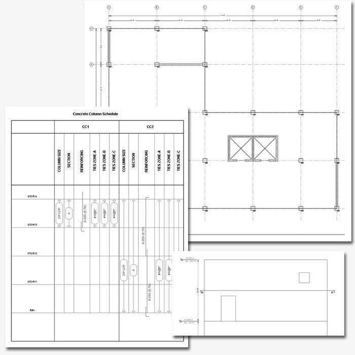
ETABS will perform comprehensive concrete detailing and scheduling for beams, columns, and walls. Users can control detailing preferences for each type of concrete detailing component.
Concrete Reinforcement Detailing
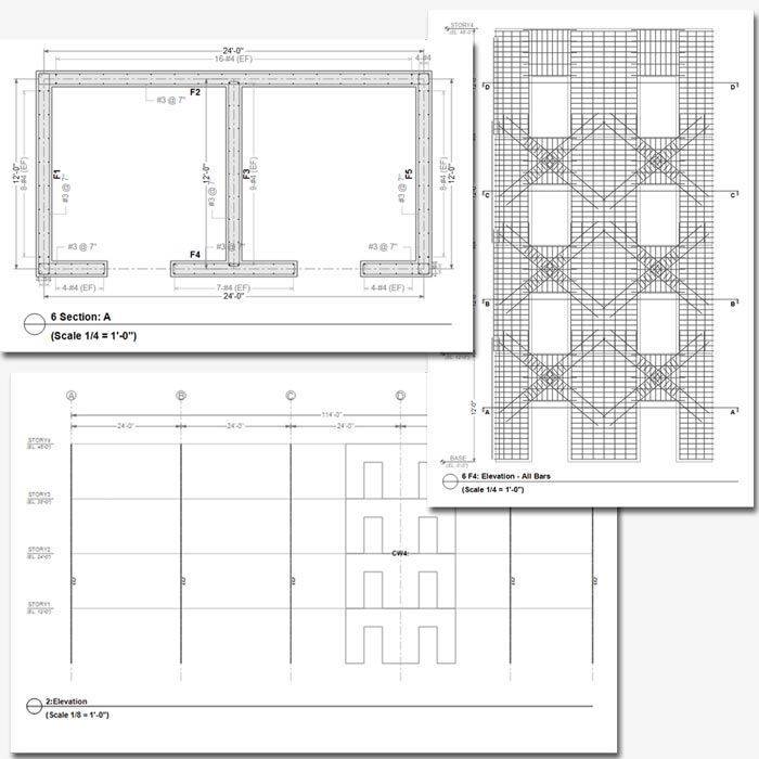
ETABS detailing will perform complete reinforcement detailing for concrete frame and shear walls based on ETABS concrete frame and concrete shear wall design results. Users have full control over rebar sizes to be used in detailing.
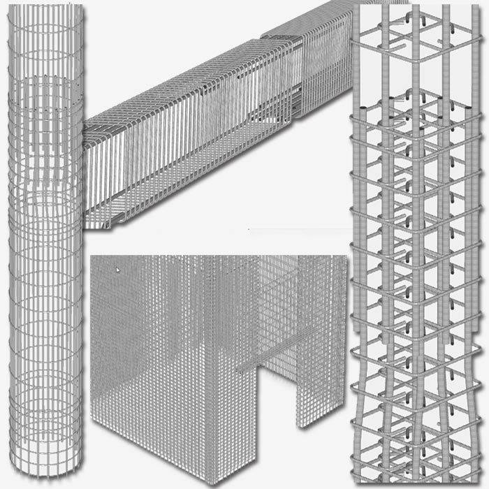
Three-dimensional renderings allow engineers to visualize bar sizes and locations. Renderings can be dragged directly onto drawings like any other component view. Renderings of reinforcement are available for concrete columns, beams, and walls.
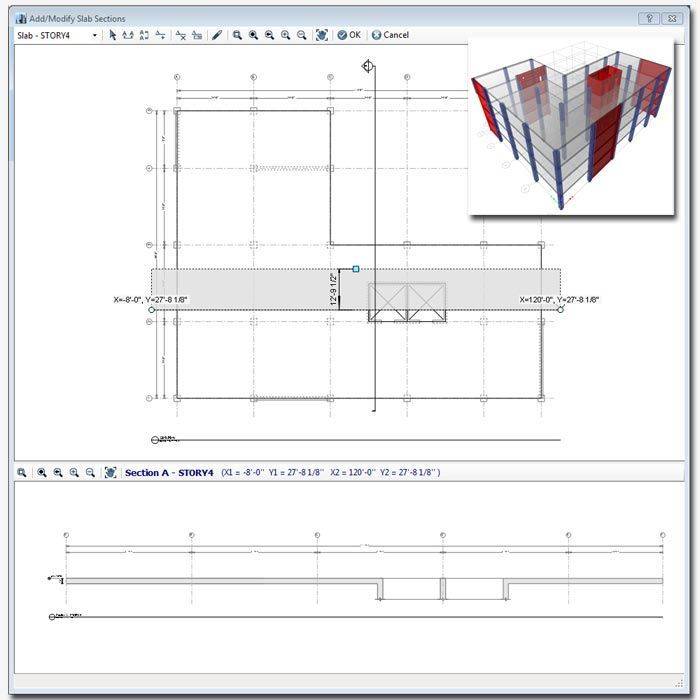
Detailing Section Cuts
While in the detailer, create section cut through slabs, beams, and mats to see instant cross sections of the part of the drawing. Users define orientation and length of the section cut and then use the section cut as a component view in another drawing.
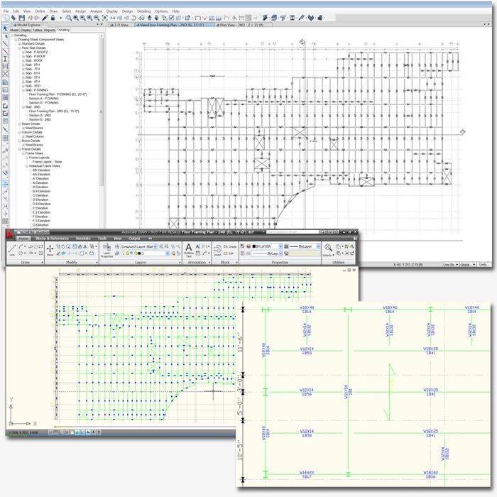
Print and Export Drawings
Print drawings and views directly to a printer or plotter, or export drawings and views to DXF or DWG format to be opened in AutoCAD or other CAD software.
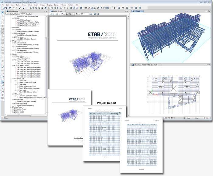
Reporting
Report Generation
The report generator features include an indexed table of contents, model definition information, and analysis and design results in tabulated format. Reports are viewable within ETABS with live document navigation connected to the Model Explorer and directly exportable to Microsoft Word.
Tools
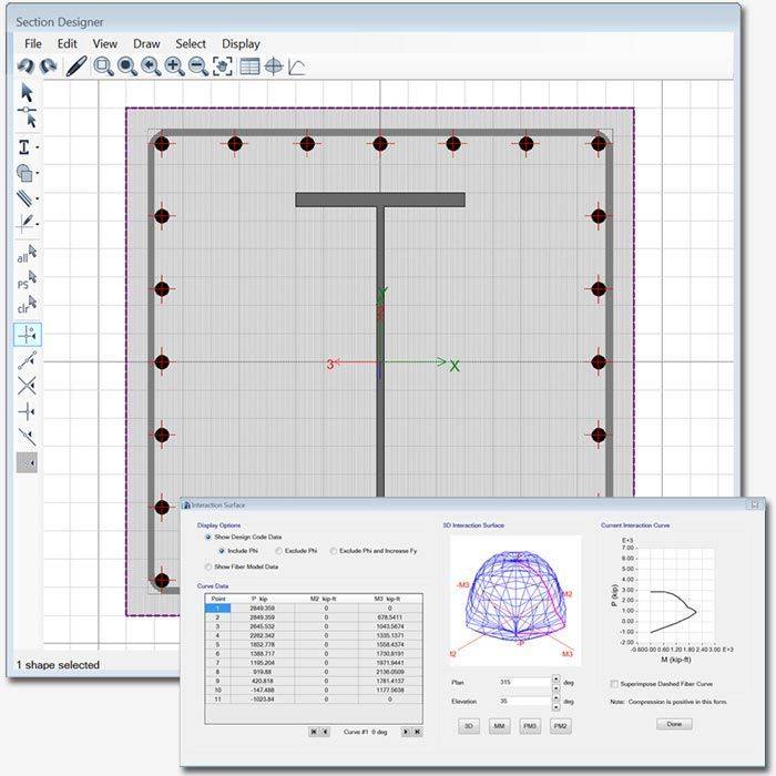
Section Designer
Section Designer is a utility that is built into ETABS. It allows users the ability to create specialized sections of any arbitrary shape and material, including rebar layout. All section properties, biaxial interaction diagrams, and moment curvature diagrams are automatically calculated.
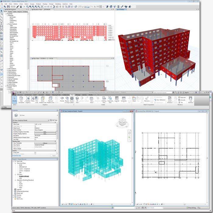
Import and Export
Supported Formats
ETABS supports many industry standards for importing and exporting data. Autodesk Revit Structure, AutoCAD (DXF/DWG), CIS/2, IFC, and SDNF are all supported. ETABS also supports exporting of a model to an Microsoft Access database.
Learn more about Building Information Modeling
ACE-Hellas S.A.
Integrated Solutions